Little portable AVR development kit

Atmel AVR portable dev kit

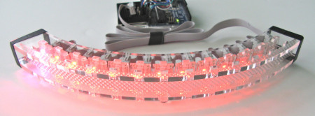
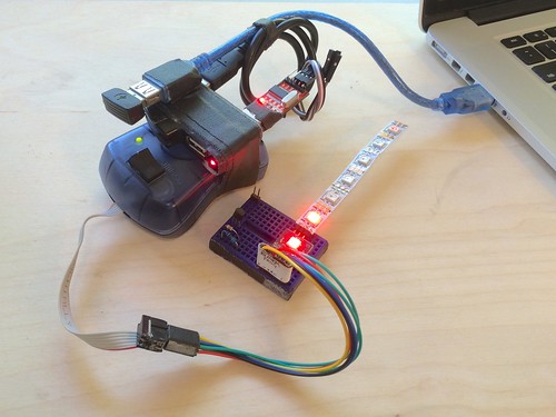
Recently a CrashSpace member asked about my little portable AVR dev platform. It’s small, compatible without avrdude hacks, and cheap enough to not worry about. Though it’s a gaffer-taped together setup, it’s served me well for about 10 years.  It’s in a go-bag about the size of my laptop’s power supply, so it’s often with me.  But people do sometimes look at me strangely when I whip this out at coffee shops. (but then I blink LEDs and all is forgiven)

The kit consists of:

  • AVRISP mkII programmer (w/ custom +5V switch on VTG (power to target))
  • USB hub, travel size 4-port
  • USB extension cable, 1 foot
  • Generic 3.3V/5V USB-to-serial adapter
  • Enough gaffers tape to bodge it all together

Just plug it all together and go.  The AVR ISP mkII is an official one from Atmel and is about $30. It looks like it may not be made any more, but there are many clones out there. The nice thing about the official one is that it works at 5V & 3V and has short-circuit protection.  I do wish the ISP protocol was faster though.  Compared to bootloaders, it’s around 5x slower. That adds up.

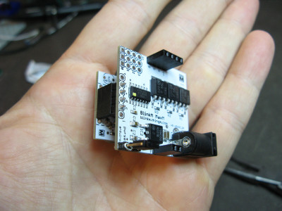
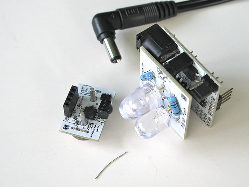
AVR Programmer VTG power

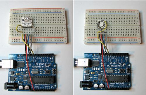
The VTG +5V switch add-on is super useful.  Normally ISP programmers don’t supply power to the target. (and shouldn’t, you don’t have to have a power supply fight)  But when doing exploratory development, having the programmer providing the power is really handy.  if you don’t want to mod your programmer, you could take an old USB cable, cut it up and run the +5V to your board.  If I were to do it again, I’d add some sort of current-limiting for those just-in-case oopses.
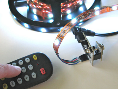
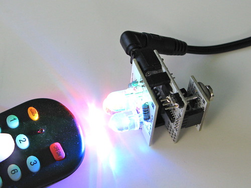
USB-to-serial

You don’t always need a serial port but when you do, you really do.  I usually keep this plugged in just in case, sort of like how I always keep a few LEDs & 1k resistors on hand.  Both are great for on-the-go debugging.

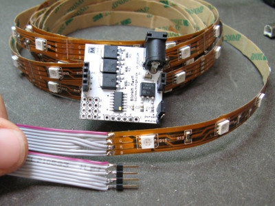
Programming adapter cables

For working with the strange, small boards I make, I have a collection adapters made from male-to-{male,female} jumpers that go from the AVRISP 6-pin connector to whatever I’m working on:

Atmel AVR portable dev kit


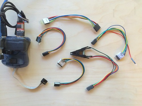
And when I work on PIC USB projects, I have a similar one for PIC.


BlinkMuino updated for Arduino 1.0 (finally)

I finally got around to updating the BlinkMuino guide for turning your BlinkM, BlinkM MinM, or BlinkM MaxM into a tiny ATtiny85 or ATtiny84 Arduino system. BlinkM boards make great tiny development boards, especially if you’re interested in driving LEDs. BlinkM MaxMs are particularly great because they have more inputs and those three beefy MOSFET power transistors. And MinMs are good because they’re super tiny, but still contain a fully-programmable computer.

Thankfully, the ArduinoISP sketch has also been updated for Arduino-1.0, meaning you can use your Arduino as an AVR-ISP programmer, like this:

blinkmuino-arduino-500px

Here’s the original video I made about BlinkMuino:

We’ll be showing off some examples of BlinkMs programmed with Arduino at Maker Faire, some say “hi”!

BlinkM Coin Cell Holder

BlinkM coin cell holder

Did you know you can power BlinkMs or BlinkM MinMs off two 3V coin cells? Here is a tiny 3d-printable coin cell and header socket holder for BlinkMs and BlinkM MinMs. It snaps together and has mounting holes to turn it into a pendant or mounting additional diffusors for the LEDs.

And you don’t need many parts to build it:
– one each of plastic pieces here (see the STL files on Thingiverse)
– two CR2032 3V coin cells
– one 4-pos female header socket (Digikey S7037-ND or equivalent)
– two short pieces of solid wire (old resistor leads, 26 gauge wire stripped, etc.)

BlinkM coin cell holder

Steps:
1. Push the 4-pin socket into the hole until it stops. It should friction-fit in without any need for glue.
2. On the bottom, feed the two wire pieces in as shown in the photos, and solder them to the two pins on the header socket. These wires become the battery terminals.
3. Bend the wire battery terminals so they make good contact with the cells.
4. Insert coin cells, snap together top piece.
5. Insert BlinkM and watch it play its light sequence.
6. To protect the back, put a small piece of gaffers tape or similar over the terminals.

For more info and pix, see this project’s Thingiverse page or the Flickr pictures.

Invisible Accent Light with BlinkM MaxM & FreeM

Sometimes you just want a little extra light in a room. With RGB LED tape, you can put light anywhere. But controlling its brightness and making it the color you want is a bit harder. A BlinkM MaxM can easily control LED tape, either as a stand-alone device, with an Arduino, or your computer via a LinkM. Stand-alone mode is great if you want a specific color or color pattern (the BlinkMSequencer makes this really easy) For this installation, I added a FreeM to the MaxM to let you control the light with a standard infrared TV remote control.

Accent Light with BlinkM MaxM & FreeM

Another nice thing about the LED tape is that when it’s off, you can’t see where it’s installed.
Here’s a video showing how it all works.

How to make this

The parts you’ll need are:
BlinkM MaxM
FreeM
RGB LED flexible tape
12V DC @ 1A power supply, you probably have this laying around
– Any universal TV remote, like this one

First up is to wire up the RGB LED tape with extension wires to go from the tape to the MaxM. This is so you can hide the MaxM where ever you feel like. Cut the wires to the length you need and solder them to the LED tape and a 4-pin male header like in the photo below. Note because the LED tape switches the Red and Green lines you’ll need to switch them because MaxM’s lines go V+,R,G,B.

Accent light with BlinkM MaxM FreeM

With that done, you should be able to hook everything up and have the MaxM drive the LED tape. The LED tape takes +12VDC. The amount of current it needs depends on the length of tape your driving. Chances are you have a 12VDC @ 1000 mA wall wart power supply from an old piece of computer gear. That should work fine.

If you want your accent light to play a constant color or color pattern, you’re now done and can place the LED tape where ever you like, like on top of a window sill. Peel off the sticker backing and stick the LED tape where it should go.
Accent light with BlinkM MaxM FreeM

Adding FreeM

If you want to go the step further and add a FreeM to give your light a remote control, then follow the steps on the Using FreeM with BlinkM MaxM page.

But it’s really not much more than plugging the FreeM into the bottom of the MaxM.

Accent light with BlinkM MaxM FreeM
FreeM with MaxM

BlinkM Cylon mkII

For Maker Faire this year I made a second version of my BlinkM Cylon: BlinkM Cylon mkII. This is not a very cost-effective way of getting a Cylon effect. It however is a good way of showing how to wire up multiple BlinkMs with a long cable, using our new WireM cabling kit for BlinkM. And unlike normal Cylon circuits, this has full RGB color effects and gradual fading.

BlinkM Cylon mkII

Here’s a quick video showing it in action.

BlinkM Cylon mkII consists of:
– 13 BlinkMs (one for each of the tribes of Kobol)
– one WireM cabling kit for BlinkM, consisting of IDC connectors and ribbon cable
– an Arduino
– two 4.7k resistors
– a single push-button
– 9VDC wall wart to power it all.
– laser cut acrylic enclosure

Below are all the files needed to recreate your own BlinkM Cylon. Click any of the images for larger versions.

Continue reading “BlinkM Cylon mkII”

Using FreeM with BlinkM MaxM

While FreeM is mostly designed to work with BlinkMs and MinMs, it can be made to work with MaxMs. FreeM cannot supply the power that MaxMs need (250mA and FreeM can only supply up to 100mA), but there are other ways. One way to do it is to power the FreeM from the MaxM’s built-in 5V power supply.

To do this, get a MaxM, a FreeM, a small scrap of wire, and a 12VDC power supply.

FreeM with MaxM

Remove the “pwrsel” jumper and wrap the small piece of wire around all three pins of the “pwrsel” jumper. Then plug the FreeM into the bottom of the MaxM and plug in the 12VDC power supply to the MaxM.

The MaxM will power the FreeM and the FreeM will control the MaxM.

FreeM with MaxM

You can also now control other LED clusters like flexible RGB LED tape.

FreeM with MaxM