
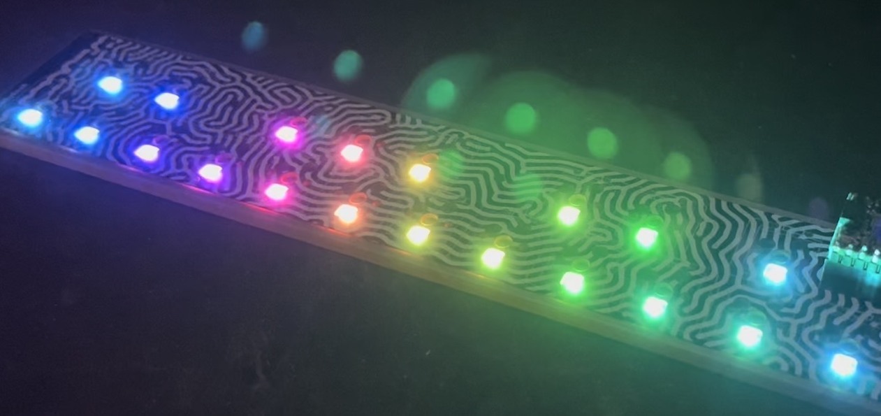
BlinkMs are a lot of fun by themselves, but they’re also little network devices, each having its own address on an I2C network. Here’s where I think BlinkM can really shine since it makes controlling multiple RGB LEDs pretty easy. For Maker Faire, I wanted to show off this facet by having a single Arduino control a dozen or so BlinkMs on a single I2C bus. The result is shown in the little video below.
Read on for how this was put together.
Overall Design
Controlling several RGB LEDs is no small task, BlinkM makes it easier and I wanted something for Maker Faire that demonstrated how simple controlling a dozen or so RGB LEDs could be. But I also wanted something that was eye-catching from a distance and robust enough for kids to play with. Since I’ve done some Cylon stuff before, a BlinkM version of that idea could be interesting and eye-catching. I had also been building my own rotary encoders and I figured a rotary encoder could be built that was pretty cheap and yet sturdy enough for thousands of kids to play with.
The overall wiring diagram is:
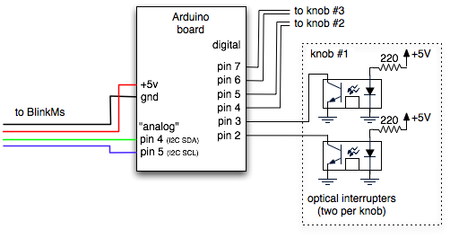
A pretty simple schematic. Arduino is at the heart of things, of course. It’s a good brain for a task like this. There are two main facets to this project: dealing all these BlinkMs and making huge rotary encoder knobs.
Cylon Eye: Connecting Multiple BlinkMs
BlinkMs are I2C devices. There can be up to 127 different devices on an I2C network.1 An I2C “network” or “bus” consists of two wires: SDA & SCL. SDA is a bidirectional data line and SCL is a clock driven by the “bus master”. In this case, Arduino is the bus master and BlinkMs are all I2C slave devices. The other two wires needed by I2C devices is power (+5V) and ground (gnd).

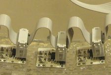
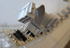
While I2C networks were not originally designed to be more than a few inches long, most I2C devices can work on I2C buses several meters in length. In this case, the total length of the I2C cable is about 1 meter (1 yard). The simple two-wire nature (four if counting power) of I2C makes wiring things up pretty simple: run a single multi-wire cable and tap off wherever you want to put a device. In this case, regular ribbon cable and IDC connectors were used.

The smallest IDC connectors that work with BlinkMs are the 2-row x 4-position kind. This calls for an 8-wire ribbon cable, so half of the wires in cable aren’t used. The IDC connectors are crimp on, so place the connector where you want it on the ribbon cable and crimp it down. Then just plug the BlinkM into the IDC connector.
Setting BlinkM Addresses
Each BlinkM has to have its I2C address set so it can be addressed uniquely. For this project, 13 BlinkMs were used, addressed from 10 to 22. The “BlinkMMulti” Arduino sketch in the BlinkM example code zip (browse it here) makes short work of addressing a handful of BlinkMs: insert BlinkM, type in new address, remove BlinkM, repeat.
BlinkM Arduino Code
Below is the relevant parts in the Arduino sketch for controlling BlinkMs. If you notice, there’s only two lines of code needed to control 13 RGB LEDs. The rest of the logic is for doing the Cylon-like back-n-forth. The “BlinkM_setRGB()” tells a BlinkM to go to a color immediately, while the “BlinkM_fadeToRGB()” tells a BlinkM to fade to a color over a period of time set by a previous call to “BlinkM_setFadeSpeed()”.
#define num_blinkms 13
#define blinkm_start_addr 10
byte curr_blinkm = 0;
int incdec = 1;  // only +1 or -1

while( 1 ) {

    [[get r,g,b values from rotary encoders]]

    byte blinkm_addr = blinkm_start_addr + curr_blinkm;

    BlinkM_setRGB( blinkm_addr, r,g,b );  // set to color
    BlinkM_fadeToRGB( blinkm_addr, 0,0,0);   // fade to black

    // prepare to move to the next cylon eye element
    curr_blinkm = curr_blinkm + incdec;
    if( incdec == 1 && curr_blinkm == num_blinkms-1 )
        incdec = -1;
    else if( incdec == -1 && curr_blinkm == 0 )
        incdec = 1;
    }
}
Pretty easy huh? And we’ve saved a lot of processing time for dealing with other things, like knobs.
Spinning Knobs: Custom Rotary Encoders
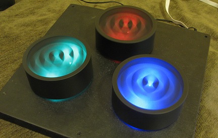
For this project, I wanted a device that wasn’t an absolute mapping of position to color amount. I didn’t want a strict teaching device, but more of a fun color exploratory toy, able to be spun like mad by kids.
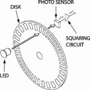
Rotary encoders are used to measure rotational amount and direction. You can find them in “infinite rotation” knobs, computer mice, robots, and lots of other things. They’re a good solution for user interface input devices when you want to make relative adjustments to a value, rather than absolute positioning (where a pot would work well). Wikipedia’s “rotary encoder” entry is a pretty good explanation of the various types of encoders. Wikipedia mentions absolute positioning encoders, a much rarer and more expensive type. Most all rotary encoders you’ll encounter are the relative positioning type. There are two main classes of relative rotary encoder implementations: mechanical and optical. Both make electrical signals when the encoder is rotated. Mechanical uses tiny electrical wipers to produce them. An optical encoder uses an optical interrupter, consisting of a light beam and light sensor.
I experimented with mechanical encoders but they had a lot of friction and their pulses-per-revolution were fairly low (12-24). I wanted a low-friction, high-resolution encoder. For low-friction this meant an optical encoder, and for high-resolution this meant a large encoder disk (since I was using fairly large optical interrupters).
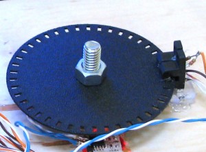
To sense the slots in the disk, standard H21A1 optical interrupters are used. These optical interrupters are simply an IR LED (”emitter”) and an IR phototransistor (”detector”) in a single package, pointing at each other. Breaking or unbreaking the beam creates a signal you can measure. If you hook them up, you can see the IR LED using a digital camera:
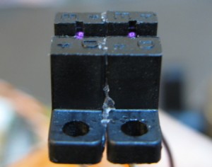
You can see the “E” and “D” markings for “emitter” and “detector” above.
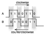
A single interrupter can measure speed of rotation by counting pulses. It can’t measure direction of rotation. But by using two interrupters and “quadrature encoding” (two output signals offset by 90º), you can measure both. The spacing between the slots, the spacing between the interrupters, and the aperture width of the LED emitter are interrelated in order to get proper quadrature output. Hopefully I’ll have a subsequent blog post describing this in more detail. :) To decode quadrature encoding, pick one of the two signals (call them “A” and “B”): when A goes HIGH, measure B. The value of B gives the direction of rotation. By counting the number of times A goes HIGH, you know how much rotation is happening. In the diagram below, follow the two signals as rotation happens either clockwise (to the right in the diagram) or counterclockwise (to the left)
Building the Knobs
The knobs are constructed out of PVC drainage caps, laser cut acrylic for hubs & diffusers, rollerblade bearings to give a smooth spin, 5/16″ bolts to act as axles, hot glue to put it all together, and a plywood base. The black, slightly rubbery texture was from the spray-on form of PlastiDip.
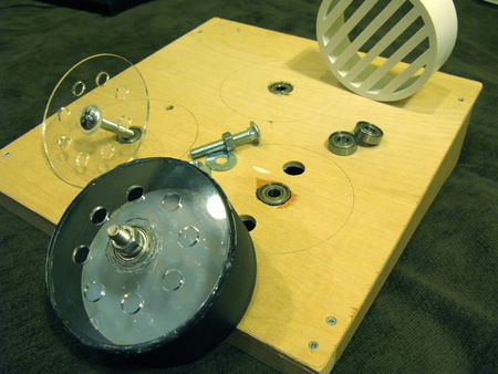
My good friend Ben Franco helped prototype many iterations of the physical design of the knobs, until we came upon the final result. He was the one who recognized that the diameter of 5/16″ nuts was just perfect enough to grasp the inner ring of a rollerblade bearing. So a 5/16″ bolt through the center of the bearing becomes the axle and the outer ring of the bearing can be attached to a stationary base, giving a smoothly spinning knob.
Rotary encoder Arduino code
When reading rotary encoders, it’s useful to think of the two signals coming out of it as a “clock” and a “data” signal. It doesn’t matter which one you treat as which, as it’s the interrelationship between the two that matters. Usually you’d use interrupts to handle reading encoders because it makes it very simple: on interrupt of the “clock” signal, read the “data” signal, and its value gives you the rotation direction. On Arduino we’ve only got one interrupt and three knobs, so polling is easier. I started with the a really good Arduino playground rotary encoder polling example and then went from there.
The relevant parts of the BlinkMCylon code for dealing with rotary encoders is below. It’s almost encapsulated enough to be a library. The “knobs” data structure contains a list of “knob” data structures, which in turn is just a holder for which pins the knob is connected to, what the last value was of that knob’s clock pin, and its current rotation value.
The “knobs_init()” function sets up the pins correctly, and by calling “knobs_poll()” as fast as possible, you can read many knobs fairly accurately.
typedef struct _knob {
    uint8_t clkpin; uint8_t datpin; uint8_t clklast; uint8_t val;
} knob;
knob knobs[num_knobs] = {
    { 2,3, 0, 0},    // first knob on pins 2 & 3
    { 4,5, 0, 0},    // second knob on pins 4 & 5
    { 6,7, 0, 0},    // third knob on pins 6 & 7
};

static void knobs_init(void)
{
    for( int i=0; i<num_knobs ; i++ ) {
        pinMode( knobs[i].clkpin, INPUT );
        pinMode( knobs[i].datpin, INPUT );
        // turn on internal pullup resistors so we don't need external ones
	digitalWrite( knobs[i].clkpin, HIGH);
        digitalWrite( knobs[i].datpin, HIGH);
    }
}

// this function must be called as quickly and as regularly as possible
static void knobs_poll(void)
{
    byte c,d;  // holder for readings
    for( byte i=0; i<num_knobs; i++ ) {
	knob k = knobs[i];           // get a knob
	c = digitalRead( k.clkpin ); // read its pins
	d = digitalRead( k.datpin );
	if( c != k.clklast  ) {      // look for clk line transition
            d = c^d;                   // xor gives us direction
	    if( d ) k.val++;           // non-zero means clockwise rotation
	    else k.val--;              // zero means counter-clockwise rotation
	    k.clklast = c;             // save the clk pin's state
            knobs[i] = k;              // save our changes
	}
    }
}
Things to Watch Out For
Having a long I2C bus containing a dozen high-power devices is a little “out there” from most I2C implementations. So there are some things to be careful of.
Power to the I2C bus
Each BlinkM draws about 60mA on power up (unless you’ve reprogrammed its power-on light script). This means that the entire I2C bus draws 13*60mA = 780 mA, 3/4 of an amp! Your power supply or voltage regulator might not be able to handle this. The voltage regulator in Arduino can just barely handle it, and it gets pretty hot if left running for a long time. If you have a lot of BlinkMs, you have to mind your power budget.
Arduino’s “Wire.h” blocking and locking up Arduino
Arduino’s (really Wiring’s) “Wire.h” library for doing I2C (aka “TWI”, two-wire interface) communication is a beautiful example of well-written, easy-to-use library. Unfortunately, it assumes everything is going perfect. If there is any problem on the I2C bus (intermittent connection, power issue like above, bad device) during an I2C transaction, the Wire library can block waiting for a response that will never arrive. The way around this is to implement an alternate I2C library that is more fault-tolerant, either by using the ATmega’s TWI hardware or by bit-banging the I2C protocol by hand. Either is kinda complex and if Wire isn’t giving you any problems, stick with it.
Tesla Coils
While at Maker Faire, our maker bench was about 50 feet from two 9-foot tall Tesla coils that ran every hour, spitting out 25kV. For some reason this tended to freeze up the Arduinos we had running stuff. Make sure you’re not located so close to any Tesla coils.
Resources & Links
- BlinkMKnobCylon.pde — Arduino source code to project
- BlinkM Cylon Flickr set
Components:
- Connector – 2×4 0.1″ spacing IDC connector, Part number “FCI 71600-308LF”, available from
Mouser – “649-71600-308LF” and Allied Electronics – “518-2312” - Ribbon cable – standard 0.05″ spacing cable for IDC connectors, like Amphenol Spectra-Strip from Mouser
BlinkM related:
Other info:
footnotes:
– 1 — there is a 7-bit address space, with 16 reserved addresses, allowing only 112 addresses. Address 0 is reserved for “general call” (broadcast), and is the only special-case address BlinkM recognizes.?
looking for more information of the construction of the underside of the knob construction
or where can i look for the complete construction build. have some parts but not sure of the total build. any help would be a help or is some one completed this project. using it for boy scout project. thanks
This particular diffuser was fluorescent lighting filters like what you might see in an office. I got it at a hardware store and laser cut it.
Hi todbot,
what material did you use for diffusing the LEDs? It looks very interesting and very opaque.
Hi Steve,
The ribbon cable is standard 0.05″-spacing stranded ribbon cable, used in PCs for decades. You need an 8-conductor strand, but you can take a larger width and peel off the 8 conductors you need. An example part number: 3M 3801/40-100 (40-conductor, 100ft spool), http://www.mouser.com/ProductDetail/3M-Electronic-Solutions-Division/3801-40-100/?qs=sGAEpiMZZMsJiFh04Lj2rnGVP%252b060guwA%252bP0nMVeObM%3d
Is there a website where I can purchase the ribbon cable you used to connect multiple blinkm’s? What I really want would be a ribbon cable that would connect to the blinkm and have the male pins on the other end, if you could help direct me in the right direction for this it would be greatly appreciated.
Hi Jelle,
In the diagrams I forgot to include the resistors, but they should definitely be there. The Arduino will hang without them.
In this example you have a picture with 3 blinkm’s but no resistors, while in the documentation you mention using two resistors (2.2kohm). Why is this? :) Thanks!