Cross-compiling C programs for C.H.I.P. Linux

blink1-chip-almost

My blink1-tool command-line program is very cross-platform. It currently supports Mac OS X 10.6.8-10.10.6, Windows XP-10, FreeBSD 10+,  most Linux distros including Ubuntu, RedHat, OpenWrt, Raspberry Pi, BeagleBone, and Linino Arduino Yun.  And I want it to work for C.H.I.P.

The NextThingCo C.H.I.P. runs a tiny Linux similar to OpenWrt or Arduino Yun.  For these systems, you don’t compile on the device itself but instead “cross-compile”: run a compiler on a computer that generates binaries for the target system.  If you’ve ever played with Arduino, you’re invoking the avr-gcc cross-compiler for the AVR chip on the Arduino board.

Setting up cross-compile with “buildroot” setups

In these small Linuxes, you use a system of Makefiles and cross-compiler suite called buildroot to build your kernel, select kernel features, and choose libraries and programs to build into your disk image. With C.H.I.P., NextThingCo has made things easy by creating  a pre-setup CHIP-buildroot and good instructions on how to get a tailored VM to run it.

Generally to compile your own program, you want to create a package for use by buildroot.  I find this a bit weighty, so I just create a section of my existing Makefile for new systems like CHIP.

The two things you need to know when doing it this way:

  • Path of cross-compiler (CC) and linker  (LD)
  • Path of any cross-compiled libraries your program needs (CFLAGS & LIBS)

Once I get the cross-compile system built with the libraries I need, I set up a Makefile sort of like this:

CCBASEDIR=/home/vagrant/CHIP-buildroot/output/host
TARGET_DIR=$(CCBASEDIR)/usr/arm-buildroot-linux-gnueabihf/sysroot

CC = $(CCBASEDIR)/usr/bin/arm-linux-gnueabihf-gcc
LD = $(CCBASEDIR)/usr/bin/arm-linux-gnueabihf-ld

CFLAGS += -I$(TARGET_DIR)/usr/include/libusb-1.0
LIBS += -L$(TARGET_DIR)/usr/lib -lusb-1.0

The above is showing what I discovered for CHIP-buildroot running inside the vagrant VM they’ve defined.  For a simple hello world program that talks libusb, the above’s all you need.  Here’s some additional discussion on simple cross-compiling for CHIP.

CHIP buildroot configuration

Unfortunately, CHIP’s firmware is currently highly pared down, so to get libusb I went to the buildroot config and added “libusb” as a package to build.

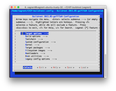
% cd CHIP-SDK
% vagrant up && vagrant ssh 
$ cd CHIP-buildroot 
$ make chip_defconfig 
$ make menuconfig

In menuconfig (pictured below), make the changes:

  • Build options -> libraries (both static and shared) -> both static & shared
  • Target packages -> Libraries -> Hardware handling -> libusb
$ make toolchain
$ make libusb  
$ make    # optional,builds new firmware & selected packages, ~60 mins

Screen Shot 2015-10-10 at 4.03.29p

The results, sigh, *this close!*

At this point I could hack up the blink1-tool Makefile and start compiling. And… It worked! It compiled! I excitedly ‘scp’d the resulting binary to my CHIP, and blink1-tool --help and… It printed!

But when I tried scanning for USB devices, it came up empty. I’ve had this problem before where a Linux libusb-based program compiles and runs but libusb can’t see any devices. Generally recompiling with the “right” libusb solves the problem, but I’m not sure what that means here.

Time to go back to a simple libusb “hello world” with maximum error checking turned on and see what’s what.

Alpha C.H.I.P. first setup impressions

IMG_6130

I recently received part of my Kickstarter reward from the famous C.H.I.P. $9 computer project.  This is the “Alpha C.H.I.P.” board that is hardware complete, but has no firmware.  So you need to install the SDK and flash the firmware yourself.  If you’re a kernel hacker (like me, I’ve been poking on Linux internals since ’98 and OpenWrt since ’06), this is pretty great. It gives one a chance to see the build process for an interesting tiny Linux system.

The steps to get C.H.I.P. up and on WiFi and accessible via ssh were very straightforward, very non-frustrating, and spelled out in the following links:

Each of those stages is pretty straight forward.  In short, these are the steps in each stage (where ‘%’ means my Mac, ‘$’ means the vagrant linux VM, and ‘#’ means CHIP command lines):

1. Install CHIP SDK

  • Install Virtual Box & Oracle Extension Pack
  • Install vagrant
  • % vagrant up && vagrant ssh
  • $ ./CHIP-SDK/setup_ubuntu1404.sh

2. Flash CHIP from CHIP SDK

  • Put jumper wire between FEL & GND pins on CHIP
  • Plug CHIP into computer’s USB
  • % cd CHIP-SDK
  • % vagrant up && vagrant ssh
  • $ cd CHIP-tools && ./chip-update-firmware.sh
  • $ cu -l /dev/ttyACM0 -s 115200
  • # hwtest
  • # exit
  • % vagrant halt

3. Get CHIP on WiFi

  • % sudo cu -l /dev/usbmodem14141 -s 115200
  • # connmanctl enable wifi
  • # connmanctl scan wifi
  • # connmanctl connect wifi_….

Here’s a complete log of everything I did, showing output for those interested: http://pastebin.com/w5pDhHAe

And here’s a pic of the FEL to GND connection needed to reflash the firmware:

IMG_6133


Note: you should have some familiarity with “vagrant” and Linux command lines if things go wrong.  If you do have a problem, just try deleting VirtualBox, vagrant, and the CHIP-SDK checkout and starting from scratch.  (I had an old VirtualBox and vagrant install that caused some issues initially)


Little portable AVR development kit

Atmel AVR portable dev kit

Recently a CrashSpace member asked about my little portable AVR dev platform. It’s small, compatible without avrdude hacks, and cheap enough to not worry about. Though it’s a gaffer-taped together setup, it’s served me well for about 10 years.  It’s in a go-bag about the size of my laptop’s power supply, so it’s often with me.  But people do sometimes look at me strangely when I whip this out at coffee shops. (but then I blink LEDs and all is forgiven)

The kit consists of:

  • AVRISP mkII programmer (w/ custom +5V switch on VTG (power to target))
  • USB hub, travel size 4-port
  • USB extension cable, 1 foot
  • Generic 3.3V/5V USB-to-serial adapter
  • Enough gaffers tape to bodge it all together

Just plug it all together and go.  The AVR ISP mkII is an official one from Atmel and is about $30. It looks like it may not be made any more, but there are many clones out there. The nice thing about the official one is that it works at 5V & 3V and has short-circuit protection.  I do wish the ISP protocol was faster though.  Compared to bootloaders, it’s around 5x slower. That adds up.

AVR Programmer VTG power

The VTG +5V switch add-on is super useful.  Normally ISP programmers don’t supply power to the target. (and shouldn’t, you don’t have to have a power supply fight)  But when doing exploratory development, having the programmer providing the power is really handy.  if you don’t want to mod your programmer, you could take an old USB cable, cut it up and run the +5V to your board.  If I were to do it again, I’d add some sort of current-limiting for those just-in-case oopses.

USB-to-serial

You don’t always need a serial port but when you do, you really do.  I usually keep this plugged in just in case, sort of like how I always keep a few LEDs & 1k resistors on hand.  Both are great for on-the-go debugging.

Programming adapter cables

For working with the strange, small boards I make, I have a collection adapters made from male-to-{male,female} jumpers that go from the AVRISP 6-pin connector to whatever I’m working on:

Atmel AVR portable dev kit


And when I work on PIC USB projects, I have a similar one for PIC.


Makerbot Replicator mods I’ve done

After two years, I think I have my Replicator (apparently the first one shipped) finally working reliably to produce >1 hour prints. Thank you @iandanforth for asking if I had a description of the mods I did and prompting me to write this.

The Replicator has been a very frustrating product. After a few out-of-the-box failures, it worked great for the first week and then rapidly deteriorated. And a few months later, the Replicator 2 was announced and support for my product rapidly evaporated. Many of the things I print are small and take <15 minutes to print, so I’ve been dealing with a <30% success rate of printing, or using other 3d printers. But I think I’ve been slowly iterating towards a reliable Replicator.

Things I have done thus far (in roughly chronological order):
* Replaced heated build plate since the original was very non-flat
* Replaced both thermocouples with parts from Makerbot
* Installed new extruder design (eliminates all filament feed issues)
* Installed Bottleworks aluminum replacement arms
* Went to three-point bed leveling by removing one of the four leveling nuts.

The heated build platform and thermocouple issues were just bad original parts from Makerbot. I still sometimes have issues with “Heating Failure #3 my extruders are losing temperature. Check my connections.” on the right extruder, but I think that’s because of either a small crack in the replacement thermocouple or it just coming loose. I’m strongly considering using this Wanhao Duplicator replacement thermocouple if the problem comes up again. At least they terminate the thermocouple with a lug instead of trusting the assembler won’t crack it when tightening.

Assuming the basic mechatronics of the printer work, the most critical fix is the new extruder design. If you’ve ever experienced your Replicator stopping extruding or only partially extruding, it’s because the original mechanism to push the filament against the extruder motor sucked. This change was so important that Makerbot themselves retrofitted all Replicator 2s with it.

MinimalMk8_preview_featured

The next most critical mod is replacing those stupid plastic cantilever arms with something sturdier. Even at room temp, those arms exhibited considerable flex. Heat up the bed and the build plate would droop a few layers, causing so. many. failed prints. With the Bottleworks Aluminum arms, the bed is now rock solid.

bc-tech-elements-09

I’ve also printed some little helper parts like extruder fan guards and leveling knob covers

Here’s some lists of other popular upgrades:
– Makerbot Users list – “Popular non-printed upgrades”
– EEWeb Gary’s blog – “Makerbot Replicator upgrades

In general, be sure to poke around the Makerbot Users mailing list. It’s got useful tips and very knowledgable people.

From that and the (now discontinued) Makerbot Operators list, I’m just waiting for the day when the entire Replicator motherboard fries itself (another story, there are many) due to bad voltage regulator design. When that happens, not sure what I’ll do.

On the one hand, maybe get a steel Duplicator 4S, maybe a Lulzbot Taz 4 modded for 1.75mm filament, or maybe support the local guys and get a Bukobot.

Portable PIC16F145x Development Platform

About a year ago, while I was developing the blink(1) mk2, I created both a PIC16F1455 development board and a little assemblage that was tiny enough to toss in my laptop bag but powerful enough to let me develop on the PIC.  I could now develop firmware in a coffeeshop!

Portable PIC16F1455 Development Platform

It consists of:

All taped together with double-stick foam tape.

The Sabrent USB hub is because it acts a partial goof-protector if I short USB power & ground and the per-port power switches make it easy to power-cycle the device I’m developing without unplugging-replugging.  The solderless breadboard is just big enough to support the addition of a few extra components.  And my dev board has female headers with male pins that stick into the breadboard, holding it securely place and making wiring to the dev board a snap.

If only MPLAB X & PICKit3 wasn’t so pokey for programming (it can take 15 seconds from the time you click “Upload”  to having your code running on the device)

BlinkMuino updated for Arduino 1.0 (finally)

I finally got around to updating the BlinkMuino guide for turning your BlinkM, BlinkM MinM, or BlinkM MaxM into a tiny ATtiny85 or ATtiny84 Arduino system. BlinkM boards make great tiny development boards, especially if you’re interested in driving LEDs. BlinkM MaxMs are particularly great because they have more inputs and those three beefy MOSFET power transistors. And MinMs are good because they’re super tiny, but still contain a fully-programmable computer.

Thankfully, the ArduinoISP sketch has also been updated for Arduino-1.0, meaning you can use your Arduino as an AVR-ISP programmer, like this:

blinkmuino-arduino-500px

Here’s the original video I made about BlinkMuino:

We’ll be showing off some examples of BlinkMs programmed with Arduino at Maker Faire, some say “hi”!

Arduino-serial: updated!

In late 2006 I wrote “arduino-serial“, mostly for myself, to help with stuff I was working on at the time. It was a very simple & small, cross-platform tool written in basic C for reading/writing serial ports.

Now nearly seven years later I still get regular questions and frustrations about it. Part of this is due to how Arduinos have changed over time. You used to have to hand-reset an Arduino board, now the act of opening the serial port resets it. This has its plusses and minuses, but it really made my original use-case of arduino-serial fail. Then there were just all the minor deficiencies of the program.

To address some of these issues, but still keep things small & light, I’ve done a bit of fix-up of arduino-serial. It’s now hosted on Github at:
https://github.com/todbot/arduino-serial/

Changes & Improvements

Some changes that I recently made to arduino-serial:

  • Separation of the application (arduino-serial.c) from the library (arduino-serial-lib.{c,h})
  • Fixed probable --read bug
  • Fixed --port open to allow re-opens
  • Added --sendline command to send a string followed by a newline
  • Added --flush command to clear out receive buffer
  • Added --eolchar option to let you specify your own end-of-line character if ‘\n’ isn’t appropriate
  • Added --timeout option to specify a read timeout (reads no longer block infinitely)
  • Added --quiet flag to make output more terse/machine-readable

Here’s what the new usage help screen looks like:

laptop% ./arduino-serial
Usage: arduino-serial -b <bps> -p <serialport> [OPTIONS]

Options:
  -h, --help                 Print this help message
  -b, --baud=baudrate        Baudrate (bps) of Arduino (default 9600)
  -p, --port=serialport      Serial port Arduino is connected to
  -s, --send=string          Send string to Arduino
  -S, --sendline=string      Send string with newline to Arduino
  -r, --receive              Receive string from Arduino & print it out
  -n  --num=num              Send a number as a single byte
  -F  --flush                Flush serial port buffers for fresh reading
  -d  --delay=millis         Delay for specified milliseconds
  -e  --eolchar=char         Specify EOL char for reads (default '\n')
  -t  --timeout=millis       Timeout for reads in millisecs (default 5000)
  -q  --quiet                Don't print out as much info

Note: Order is important. Set '-b' baudrate before opening port'-p'.
      Used to make series of actions: '-d 2000 -s hello -d 100 -r'
      means 'wait 2secs, send 'hello', wait 100msec, get reply'

Using arduino-serial

arduino-serial has always been designed so you can “pipeline” commands/options, but it wasn’t implemented very consistently. It’s a bit better now. You can do multiple send/read pairs, even use multiple serial ports, all from a single command-line invocation.

For example, if you have the “SerialCallResponseASCII” sketch from the Communications examples loaded onto your Arduino, you can run commands to take multiple data readings. In the example below, the order of operations are:

  1. serial port is opened (at 9600)
  2. the string “A” is sent (a single-byte)
  3. the first line is read
  4. sleep for 1000 milliseconds
  5. send “A” again
  6. read second data line
  7. flush read buffer (just to show we can)
  8. send “A” a third time
  9. and take a final reading
laptop% ./arduino-serial -b 9600 -p /dev/tty.usbmodemfd131 \
            -s "A" -r  -d 1000  -s "A" -r  -F  -s "A" -r
send string:A
read string:465,396,0

sleep 1000 millisecs
send string:A
read string:358,352,0

flushing receive buffer
send string:A
read string:307,305,0

The flush was put in there to demonstrate that you could flush the receive buffer mid-command if you wanted. It’s not required, but might help some situations.

To use multiple serial ports, you can do something like the below, which opens up one serial port at 9600 bps, does a send & receive, then opens another at 57600 bps and does a send & receive on it:

laptop% ./arduino-serial -b 9600 -p /dev/tty.usbmodemfd131 \
        -s "A" -r \
        -b 57600 -p /dev/tty.usbserial-A800f8ib \
        -s "hello" -r