At CrashSpace we have a publicly-viewable “sign” at https://crashspacela.com/sign/ to let members know when the space is open. This sign page is updated by a big button in the front room. Press it, the sign page updates, and you’ve promised to be in the space for an hour.
But last month, the button broke. So I made a new one based on an ESP8266 WiFi module, WS2812/Neopixel LEDs, and a custom PCB fabbed on an Othermill. Schematics, PCB & firmware at: github/todbot/crashspace-bigbutton.
See below for:
- construction details
- PCB techniques for Othermill
- “sacrificial Neopixels” for 3v3 to 5V level conversion
Some history
The first version of the BigButton I did back in 2010 consisted of an Arduino in a taplight tethered to a netbook running a Perl script. Last year it was upgraded by a member to a Spark.io SparkButton (early version of the Particle Photon Internet Button kit but not using the better chip of the Photon) with a custom 3d-printed case. That upgrade resulted in a much simpler and smaller Button than my original. It was great. But occasionally it would drop its connection and need a reboot. Then a month or so ago it just stopped working entirely. I ended up recreating the functionality with a Photon but found the environment limiting, particularly the near-requirement of an online compiler.
The New BigButton
For the new BigButton I went with the Wemos D1 Mini ESP8266 WiFi board. This is essentially a tiny version of the standard NodeMCU board that contains a USB-to-serial interface and the necessary support circuitry to control and reprogram the ESP8266 module. It’s easy-to-use, stable, and great. Instead of programming it directly, I figured I’d try the ESP8266 Arduino core and write an Arduino sketch.

The sketch uses the wonderful ArduinoJson library. It’s pretty memory efficient and uses clever C++ operator-overloading to let you write JSON parsing code like this:
// jsonstr = '{"is_open":false,"minutes_left":-920.45,"button_presses":[]}'
JsonObject& root = jsonBuffer.parseObject(jsonstr);
bool is_open = root["is_open"];
double minutes_left = root["minutes_left"];
Custom PCB Carrier Board
The first BigButton used flexible LED strip hot glued into a repurposed tap light. That worked but I wanted an excuse to do another Othermill-based PCB, so I created a carrier board that had 12 WS2812 LEDs and a socket for the D1 Mini board. There are breakouts for testing the WS2812s and the button inputs. It also has footprints for buttons and mounting holes for either standoffs or guide rails.
Otherwise the schematic is pretty straightforward.


Sacrificial Neopixels: Converting ESP8266 output for WS2812 LEDs
One interesting thing about the schematic how the ESP8266 (a 3v3 device) manages to control 5V WS2812/Neopixel LEDs. Some WS2812s can be driven by 3v3 logic HIGH, but it’s iffy. The standard solution is a level-shifter buffer to convert 3v3 HIGH to 5V HIGH.
The technique used on the BigButton board, however, is to create a “sacrificial” LED powered not by 5V directly but via a stepped-down voltage from a standard signal diode (with its 0.7V voltage drop). This creates an approximately 4.3V power source that is high enough to drive the LED but brings its concept of logic HIGH (>70% of Vcc) down to what a 3v3 device will output. Basically, we’re building a fakey intermediary power supply for a single LED. The rest of the WS2812 LEDs are driven by 5V.
Here’s a diagram perhaps making the idea more clear:

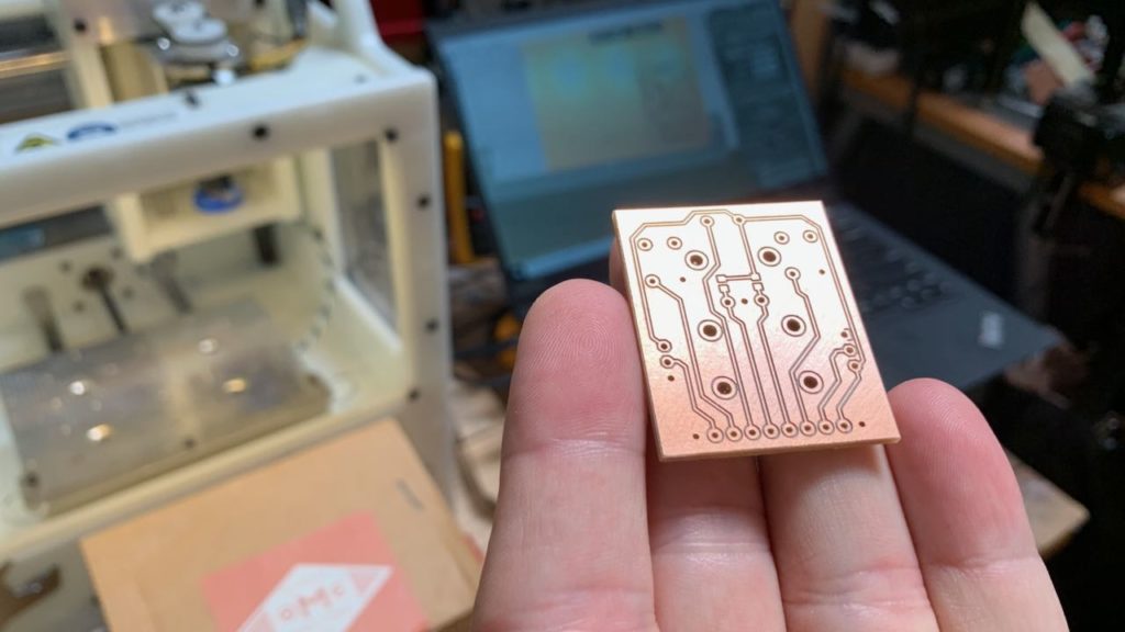
Othermill design considerations
I wanted the PCB to be millable on an Othermill, so that meant modifying my standard PCB design techniques. There are a few reasons for this. For instance, since this board has no soldermask, I want to maximize spacing between copper traces to avoid solder bridges. Also, I want to minimize the use of endmills smaller than 1/32″ because they are fragile and take a long time to mill.
Thus, the techniques I use are:
- Increase trace width 16 mil (0.016″)
- Add ground plane, set its Polygon->Isolate value to 32 mil (0.032″)
- Single-sided only design (or minimize back-side traces)
- Space components out to enable easy soldering
The result is below. The Wemos D1 Mini board is mounted on the backside of the board so it doesn’t affect light output.
For the enclosure I reused the original 2010 BigButton taplight enclosure because its diffuser is really pretty good. Plus my Fusion360 skills weren’t up to making a custom 3D printed enclosure.
The PCB is mounted on standoffs that are then screwed into the modified taplight. The taplight’s switch is reused as the button input.


The final result is flashed with WiFi credentials, wired for power, and installed on the wall.
CrashSpace BigButton w/ ESP8266, WS2812/Neopixel, using Othermill