

Bionic Arduino is a set of four 3-hour classes in November 2007 hosted by Machine Project and taught by Tod E. Kurt. It is an introduction to microcontroller programming and interfacing with the real world using the Arduino physical computing platform. It focuses on building new physical senses and making motion with the building blocks of robotics, using Arduino as a platform.
In the class, participants are shown and experiment with the Arduino’s capabilities and learn the basics of common microcontroller interfacing, such as: digital output to control lights and LEDs, digital input to read switches and buttons, analog output to control motor position or LED brightness, and analog input to read sensor inputs.
The class assumes no previous electronics knowledge, though it does assume a little programming knowledge. No soldering is needed during the class, as all circuits are built with solderless breadboards.
Class Notes
- bionic_arduino_class1.pdf (7.7MB PDF)
- bionic_arduino_class2.pdf (9.2MB PDF)
- bionic_arduino_class3.pdf (4.9MB PDF)
- bionic_arduino_class4.pdf (6.6MB PDF)
Arduino Sketches Used in Class
- Blink – Blink an LED
- Fading – Vary the brightness of an LED
- FadeOrBlink – A button to switch between Fade or Blink
- CandleLight – Random behavior emulates candles
- PotDimmer – Use a pot to change brightness
- RGBMoodLight – Control RGB LED algorithmically
- RGBPotMixer – Control RGB LED with a pot
- SerialHelloWorld – Say hello to serial
- SerialReadBasic – How to read serial values
- SerialReadBlink – Change blink rate with serial commands
- SerialRGBLED – Change LED color with serial commands
- SoundSerial – Use serial input to control piezo buzzer
- PlayMelody – Play a pre-defined melody
- Theremin – Use a photocell & piezo as a theremin
- SerialMotorSpeed – Control motor speed over serial
- PiezoKnock – Make a piezo buzzer a sensor
- PiezoMotorPulse – Turn on a motor if knocked
- PotSend – Send binary pot data (for Processing)
- ServoSimple – Move a servo back and forth
- ServoSerialSimple – Control servo from serial port
- ServoSerialBetter – A better way to control a servo
- NunchuckPrint – Print sensor data from Wii Nunchuck
- NunchuckServo – Use Nunchuck to control a servo
- bionicarduino-sketches.zip – All Arduino sketches zipped up
Processing Sketches Used in Class
- ArduinoReadCircle – Circle sizes changes from Arduino knob
- ArduinoBounce – Ball size changes from Arduino knob
- ArduinoSounds – Trigger sounds from Arduino knock sensor
- bionic-processing-sketches.zip – All Processing sketches zipped up
Parts Suppliers, New
- SparkFun — Arudino board and shield, and many other neat gizmos.
- Jameco — General electronic parts, easy-to-use, also has computer parts.
- Digikey — Exhaustive parts supplier. Cheaper than Jameco usually, has more variation, more hard-to-find parts.
Hi Todd,
Not to blatantly advertise my own product, but if you’re looking to drive 3 RGB LEDs with Arduino, perhaps the easiest solution are three BlinkMs.
If that’s not what you’re doing, then you can recreate PWM by hand using really fast loops, like how the Sevo library works.
I need at least 9 pwm enabled pins for a project I am working on using LEDs. What is the best way to get this done but have all outputs independent of each other?
I looked around and have not found any solutions that did not seam like overkill.
Thanks you for your time.
I know some of the guys at Dorkbot. I am there, dude.
thanks
Oh…I forgot
As some one approaches the piece, a motor will turn on the closer a viewer gets, so that when a viewer is 6″(or so) away, all the motors are on, but at, say 4 feet, only one is on. I am looking to learn, so any suggestions on code I can hack…
int ledPin = 13; // select the pin for the LED
int i=0; // simple counter to show we’re doing something
void setup() {
pinMode(ledPin,OUTPUT); // declare the LED’s pin as output
Serial.begin(19200); // connect to the serial port
}
void loop () {
Serial.print(i++);
Serial.println(” Thanks Again !”); // print out a thanks
digitalWrite(ledPin, HIGH);
delay(500);
digitalWrite(ledPin, LOW);
delay(500);
}
//Christopher//
Hi Christopher,
You should check out the Arduino Workshops forum on the Arduino site. In fact, it looks like there’s an Arduino workshop at the Chicago Dorkbot meeting on January 23rd!
I am learning the arduino…I am over loaded with info…I am looking for some one to do this with…are there any classes or seminars in the Chicago area ?
I am working towards controlling a set of motors that turn on the closer some one approaches the piece. Do you recommend the ultrasonic range finder, or the Infrared range finder ?
Much thanks
Christopher
Hi Job,
You want to be able to turn on multiple LEDs with one digital out? If you’re using red LEDs, you can put two (sometimes three) in series instead of just having one LED.
If you want to drive many more than that (or what to drive non-red LEDs), then you would use a transistor. See page page 20 of the Bionic Arduino Class3 notes for a brief description of this. The schematic would be:
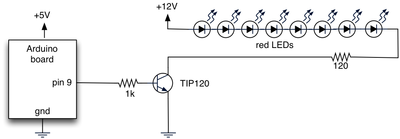
You would need to adjust the number of LEDs and the resistor value depending on the color of the LED using Ohm’s Law (red LEDs are ~1.2V, green ~2.0V, and blue ~3.4V). I can help with some example scenarios if you like.
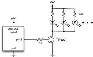
Alternatively, you can run the LEDs in parallel, by duplicating the LED+resistor sub-circuit as many times as you want, until you reach the current limit of your transistor. This has the advantage of you can keep adding LEDs without tuning resistor values and being limited by your source power. The above example uses 12V so you could stack LEDs, but the one below can just use the 5V on the Arduino board for as many LEDs as the Arduino has power for and the transistor has current capability for. The downside is you need a resistor for each LED.
I really liked your lessons, only thing i want to know now is how i can use more led’s on one digital out….
your help oould be much appreciated.
greetz Job
Thanks! I’ll check into that before I go replacing the joystick with bend sensors…. :D
Hi Jerome,
You’ve discovered one of the hallmarks of sensors: noisy data. To smooth out the noise, the most common thing to do is to take a running average of the last N readings.
There’s an Arduino tutorial about this:
http://www.arduino.cc/en/Tutorial/Smoothing
Hi Tod,
Thanks so much for posting all this info- it’s been a tremendous learning experience and a lot of fun.
I was able to modify the NunchuckServo code so I could access the other controller inputs- now I have multiple servos and both the buttons working- woohoo! But I do have a question about trying to smooth out the servo motion. I’ve changed the refresh rate and that definitely helped- any other suggestions?
Thanks!
Jerome
Hi Todbot,
Thank you, for the best class of electronic I have ever read.
Zmpulse (from France)
Hi Zac,
Thanks, I’m glad you’ve found the class notes useful.
Controlling multiple RGB LEDs can be difficult, especially if you want to control their brightness. There are LED driver chips out there, but they can be hard to use.
I’ve been developing a solution to this problem that is called a “Smart LED”. You can read about them and the general concept of smart interface components in my Smart Interface Components talk slides.
In about a month we’ll have a type of Smart LED called “BlinkM” for sale. Each BlinkM is a smart RGB LED with 24-bit color control and an I2C serial interface, so you can control 127 BlinkMs with a single Arduino.
Hi Todd,
Great site. This has has been a tremendous help in finally understanding microcontrollers. I am an absolute newbie and now have my LEDs blinking morse code!
Question: How would you control multiple RGB LEDs with only the Arduino’s limited PWMs? Is the expandable without purchasing multiple Arduinos?
Thanks again!
Zac
Hi Christin,
If you’re using an Arduino Diecimila, opening the serial port will reset the board on Mac OS X & Linux, so the pin13 blink is probably that. (and that’s a good thing) After opening the port, you need to wait a bit (around 1.5 seconds on Diecimila or 5 secs on older Arduinos) for the bootloader to timeout before you can send or receive stuff.
What sketch are you trying out? I’d suggest trying out something like the SerialHelloWorld and see if you can just receive characters being spit at you by the Arduino.
Hey Todd,
I just found an osX implementation of php_serial.class here: http://www.geekymedia.com/phpserial.html as the original class didn’t include calls for darwin/osx.
I am running into weird problems with it, however, and have emailed the author to see if he has any suggestions (basically, it doesn’t appear to be opening a serial port, but every time I try to, I see my pin13 LED blink, so it must be doing something)
Hey one of the guys at the class mentioned ITC on Olympic in Korean Town as a cool place to pick up components and such. I can confirm this, and recommend it! The prices are… well it’s retail, so they aren’t fabulous, but they have a lot of good stuff. I didn’t see much in the way of ICs, but there were lots of LEDs/ Resistors/Caps/etc. a handful of kits, some tools, a decent wire section, and a big audio area that was mostly focused on the car. Worthy of a quick trip into K-Town, and a notable place to have on your list. Happy Monday!
32-channel servo controller
umm… sitting in your class now.
but but …