Did you know you can run Arduino programs on tiny BlinkM Smart LEDs? It might make BlinkM the smallest Arduino so far. To use a BlinkM as an Arduino, all you need is the free Arduino software, a low-cost AVR programmer, some wire, and a BlinkM.
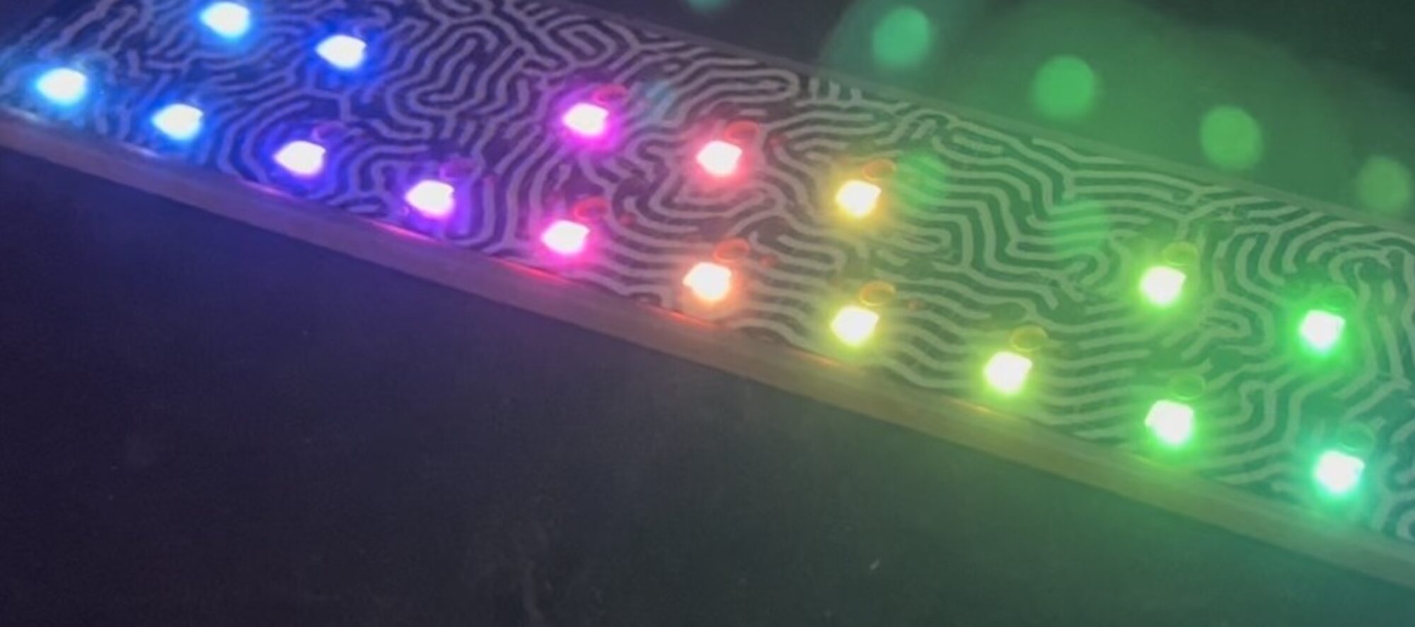
Here’s a quick video showing how it all works.
BlinkM Capabilities as an Arduino
The BlinkM board doesn’t have nearly the I/O pins and other features of a real Arduino board. But it is very tiny. Here are its capabilities:
– 0.4″ square (MinM), or 0.6″ square (BlinkM)
– 8MHz clock speed
– 8k bytes Flash ROM (4kB on ATtiny45)
– 512 bytes RAM (256 bytes on ATtiny45)
– 512 bytes EEPROM (256 bytes on ATtiny45)
– 5 I/O lines total, partitioned as:
– 3 high-brightness LEDs in RGB package
– 2 digital I/O lines
– 1 analog I/O line (shared with digital)
And if you snip off the RGB LED, the three I/O lines used by it can be used as analog or digital inputs.
Most libraries will probably not work without some modifications. You don’t get a hardware serial port either, but SoftwareSerial works.
Software Setup
To enable the Arduino software to program BlinkMs, you’ll need to teach Arduino about new “Boards”. This is done via a set of config files and AVR core code. This work has been done by the High-Low Tech group at MIT and Alessandro Saporetti.
The BlinkMuino.zip zip file contains everything you need. This zip file works for Mac OS X, Windows, and Linux.
Unzip BlinkMuino.zip and copy the resulting “hardware” folder into your Arduino sketchbook folder. You can find the location of your sketchbook folder from the “Sketchbook location” field in the Arduino Preferences . On Mac OS X, this is usually “/Users/yourname/Documents/Arduino“. Once you copy the BlinkMuino “hardware” folder into your sketchbook, the resulting folder path should look like:
“/Users/yourname/Documents/Arduino/hardware/blinkm“.
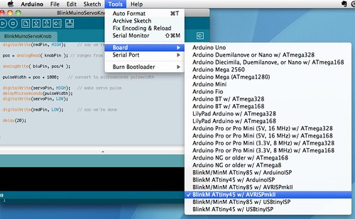
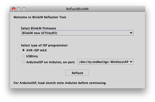
Restart the Arduino software and the “Tools” -> “Board” menu should now have entries for BlinkMs. There are three sets of entries, depending on the type of BlinkM and programmer you have. Select the entry that is correct for your hardware.
Hardware Setup
You will need an AVR-ISP programmer to program the BlinkM boards. If you have an Arduino board, the ArduinoISP sketch turns the Arduino into an AVR-ISP programmer. However, it doesn’t work for all Arduino boards. Or you can use a regular AVR-ISP programmer. These are fairly low-cost: the Atmel AVRISPmkII is 35 USD, while the Adafruit’s USBtinyISP is 22 USD.
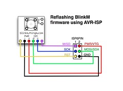
With a programmer acquired, wire up the BlinkM to it. If using a regular AVR-ISP programmer, it should be wired up like below. The intro video shows a practical method of using a breadboard and jumper wires to convert the 6-pin AVR-ISP connector to something a BlinkM can use. Note that some programmers do not supply power to the BlinkM, so you may need to run power too.
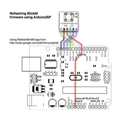
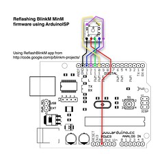
If using AruinoISP, the hookup is as below. See the diagrams and photos on the ReflashBlinkM page for details.
Using BlinkM as an Arduino
Now load up one of the example sketches located in the “hardware/blinkm/examples” folder of your Arduino sketchbook.
When you press the “Upload” button, the Arduino software will use send your program to the AVR-ISP programmer you’ve hooked up and it will program the BlinkM.
While the BlinkM is being programmed, its blue LED will flash. Once it stops flashing, the BlinkM starts running the Arduino sketch. At this point you can disconnect the BlinkM from the programmer and use it however you like. It runs stand-alone, no computer or Arduino board required, just power.
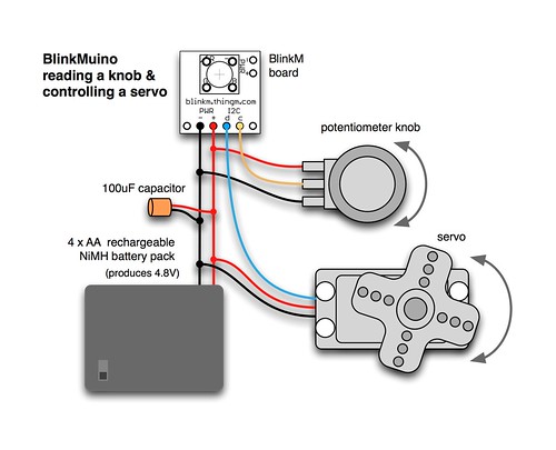
As an example, below is the “BlinkMuinoServoKnob.pde” sketch shown in the video. It assumes it is hooked up to a potentiometer knob and a hobby servo as in this diagram:
/*
 * BlinkMuinoServoKnob -- Control a servo with a knob
 * 2011 - Tod E. Kurt - https://todbot.com/blog/ - http://thingm.com/
 */

// BlinkM / BlinkM MinM pins
const int redPin = 3;  //
const int grnPin = 4;  //
const int bluPin = 1;  // PWM, will blink when programming
const int sdaPin = 0;  // PWM, 'd' pin, can be digital I/O
const int sclPin = 2;  // A/D, 'c' pin, can be digital I/O, or analog input

const int servoPin = sdaPin;
const int knobPin  = sclPin;

int pos;
int pulseWidth;

void setup() {
  pinMode(redPin, OUTPUT);
  pinMode(grnPin, OUTPUT);
  pinMode(bluPin, OUTPUT);

  pinMode(servoPin, OUTPUT);
  pinMode(knobPin, INPUT);

  digitalWrite(grnPin, HIGH);     // do a little "hello there" intro
  delay(100);
  digitalWrite(grnPin, LOW);
}

void loop() {
  digitalWrite(redPin, HIGH);     // say we're doing something
  pos = analogRead( knobPin ); // ranges from 0-1024
  analogWrite( bluPin, pos/4 );
  pulseWidth = pos + 1000;    // convert to microseconds pulsewidth

  digitalWrite(servoPin, HIGH);   // make servo pulse
  delayMicroseconds(pulseWidth);
  digitalWrite(servoPin, LOW);

  digitalWrite(redPin, LOW);      // say we're done
  delay(20);
}
Getting BlinkM back to Factory Firmware
Programming a BlinkM board with Arduino sketches erases the normal BlinkM firmware. If you want that functionality back, there is a collection of BlinkM factory firmware files and an application to program them called ReflashBlinkM. Use this to get your BlinkM back to factory-fresh conditions.
Have Fun!
Using the BlinkM board as a general purpose microcontroller board is a real blast. It’s astounding being able to reprogram something so small with the easy-to-use Arduino software. If you develop something neat with a BlinkMuino, let me know in the comments.
TheRafMan, this is very cool! And you may have noticed you got on Hackaday. :)
As for the differences between the ATtiny85 Arduino config at HLT vs the BlinkM Arduino config presented here, the only differences are: the clock speed set to 8MHz instead of 1MHz (BlinkMs run at 8MHz) and I fixed up the broken analogRead(), which used ADx numbering instead of Arudino pin numbering.
As far as PWM, ATtiny85s only have two hardware PWM channels usable by analogWrite(), on pins 0 and 1, aka the ‘d’ pin and the blue LED pin on BlinkM. So you won’t be able to use analogWrite() on any LED pins except for blue.
@craig
I ran into the same issue myself and could not figure out what the problem was until I found this post on how to program the ATtiny with an Arduino: http://hlt.media.mit.edu/wiki/pmwiki.php?n=Main.ArduinoATtiny4585
By choosing the ATtiny85 instead of the BlinkM, I was able to get it to work on all three colors, HOWEVER the clock speed is different, it runs 8 times faster so keep that in mind. I took a quick peek at the configuration files and it does look like they use different clock speeds settings between the ATtiny85 (w / Arduino as ISP) and the BlinkM/MiniM ATtiny85 w / Arduino ISP but did not get a chance to play with them.
Hello Tod,
here is something I made using your neat hack:
http://www.instructables.com/id/Smart-Push-button-for-Garage-Door/
Basically this hack turns a BlinkM into a fancy garage door indicator by inserting it inside a push-button and by adding a magnetic door switch to activate it, hope you like it.
This is the code I’m using for the blue fadein/out which works well, but the same code refuses to work properly for red and green which is a pity as it’s ultra smooth fading
  for (i = 0; i  0; i--) { // loop from 255 to 1 (fade out)
    analogWrite(bluLED, i); // set the LED brightness
    delay(10);           // Wait 10ms
  }
}
Hi Todd,
Everything working fine on my MinM ATTiny85 and running your examples ok.
Any idea how to slow the fading down on the included example, as I’ve tried putting a delay (10) in for red and green led’s which seems not to work so any help appreciated.
Strangely the blu LED fade works fine with analogWrite, but the red and green do not.
for(byte i=1; i<100; i++) { byte on = i; byte off = 100-on; for( byte j=0; j<100; j++ ) { digitalWrite(grnPin, HIGH); // digitalWrite(bluPin, HIGH); delayMicroseconds(on); delayMicroseconds(on); digitalWrite(grnPin, LOW); // digitalWrite(bluPin, LOW); delayMicroseconds(off); } } // fade down for(byte i=1; i<100; i++) { byte on = 100-i; byte off = i; for( byte j=0; j<100; j++ ) { digitalWrite(grnPin, HIGH); //digitalWrite(bluPin, HIGH); delayMicroseconds(on); delayMicroseconds(on); digitalWrite(grnPin, LOW); // digitalWrite(bluPin, LOW); delayMicroseconds(off); } } IThis is a great hack, and it came at the right time for a small project I have in mind, (I will give details once I complete it).
BTW, if anyone is having the error message “avrdude: stk500_getsync(): not in sync: resp=0x15” when using ArduinoISP to program the BlinkM, it is easily fixable by putting a 100 ohm resistor between the reset pin and 5v of the Arduino after loading the ArduinoISP, it worked great with my Freeduino and Ardweeny.
Very Nice!
Will have to exchange the use of a atmega in one of my boards for an ATTiny and use this core instead of AVRdude (for beginners). Major plus is that ATTiny45/85 are nice, cheap, small, and come in DIP!
@Stefan
Yes it is possible IF you rip out the RGB-led and put an Op-amp circuit to it and feed the analog value back in the blinkM (could use digital-in too so the the pin will fire when light to the r-g-b-led is over a threshold value)
otherwise the the signal is too small to be detected…..
Hey,
I had an idea. Any way to use the RGB led as a sensor? Hear of this being done with single color leds. 2 blinkMs with 1 sensor and 1 servo might make a cool little
braitenburg bot.
just my 2 cents
best Stefman