
LEDs should be smarter. Sure we have flashing LED assemblies and even rudimentary RGB-flashing discrete LEDs. But LEDs themselves are predominately just dumb lights. There’s no real reason for this. Fab processes for microcontrollers and LEDs aren’t that dissimilar. It should be possible to have both in a single LED-like package.
There is a glimmer of this happening, like the “RGB LED Slow Colour Change” LEDs you can get. You can see an example of these being used on the Embarrasingly Easy CaseMod. Unfortunately you can’t change the cycle time or anything else of how these LEDs work. So let’s make our own. These prototype Smart LEDs will necessarily be larger than a production run, but the size is getting close, giving us a feeling for how we might use them.
Smart LED Designs
Making a Smart LED just means adding a micrcontroller to an existing LED. Alex Weber created a neat version of this with his Programmable LED that has a blink pattern programmed by you via its integrated photocell.
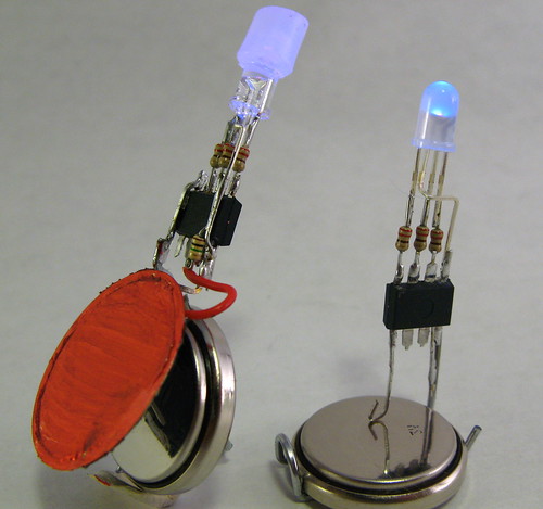
The circuits for the Smart LEDs on this page are essentially the same as Alex’s, except that an RGB LED is used instead. Electrically, an RGB LED looks like three LEDs. An Atmel AVR ATtiny13 is the microcontroller brain.
In this design the ATtiny13 is running at 4.8MHz from its internal oscillator with no clock scaling. That means it draws only about 1mA of current. The LEDs draw around 10mA for each color, so 30 mA total. But that’s a maximum, and by using PWM the average power consumption is a good deal less.
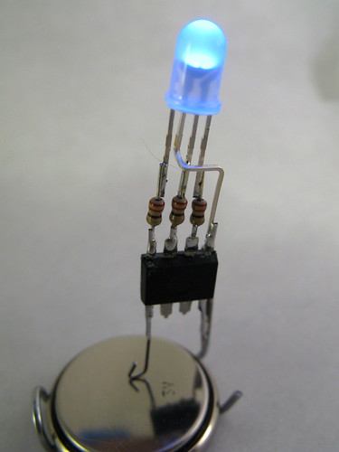
If you know how to program an Arduino, you can program one of these chips. The result is soldered together directly without the need of a PCB. Its only input is two power pins. Hook these pins up to any voltage between 2.7V and 5.5V to light it up.
The particular LED used for this Smart LED is a common anode one with a diffused lens. The common anode is connected to the positive power connection instead of ground, and all the on/off logic for the LED in the software must be flipped.
The software for this Smart LED is just a simple 3-channel software PWM color fade similar to Clay Shirky’s Arduino example.
Adding senses to the Smart LED
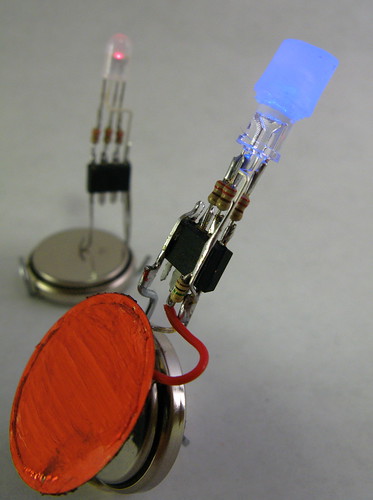
As with Alex’s Programmable LED, adding senses to a Smart LED is easy. Instead of a photocell, let’s add a piezo element ripped from an old buzzer and used as a knock sensor. Using piezos as knock sensors is easy. By soldering the piezo directly to the Smart LED, a nice little package is made.
The algorithm initially implemented for this Smart LED is a RGB color change like before, but if the piezo is struck, the LED turns white for a moment, then decaying down in brightness before returning back to the color changing.
In this case, a common-cathode RGB LED with crystal-clear lens was used with a small diffuser on top.
RGB LEDs and Diffusers
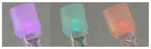
Most RGB LEDs you can find have a really narrow viewing angle, making them useful for flashlights maybe but not for ambient indicators. And because the red, green, and blue LED die are off axis from the integral lens that creates the narrow viewing angle, you don’t get very good color mixing. Sometimes you can find diffuse integral lenses on RGB LEDs (like the smaller smart LED pictured) but more often the lenses are crystal clear.
By placing a small dab of diffusive material on top of the LED, the light is mixed and diffused. In this case, a cylinder of unmelted hot glue was used:
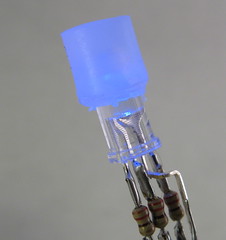
And then you can get a wide range nicely mixed colors:
Smart LED Prototype Programming
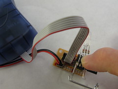
The fun part about building these devices is that you can reprogram them after you’ve constructed them. That is, if you’re careful and leave the back of the chips exposed. With the backs exposed you can press them only an 8-pin socket that is connected to a standard AVR ISP connector.
Smart LED Prototype Software
The software is really pretty easy stuff once you’re over the hurdle of AVR programming in general. As mentioned above, Arduino is a great place to start and you can review the Spooky Arduino class notes for a directed introduction.
After you know Arduino, it’s a small step to program AVR chips directly. You’ll need something like the AVRISP mkII programmer (about $35 from Digikey).
This particular software is kinda tricky because it implements software PWM. The software PWM code is directly borrowed from Atmel Application Note #136, “Low-Jitter Multi-Channel Software PWM” by Andy Gayne. I’ve successfully used the code to scale up to 16 software PWM channels and here, down to 3. At the 4.8MHz clock, the PWM rate is about 73Hz, which is low enough to cause beating with the 30 Hz rate of the video below. The PWM frequency could be increased with a few timer changes, but the rate isn’t visible to humans and any changes away from a known-working system should be avoided.
The software:
The code was quickly thrown together from another project, so the comments are either non-existent or misleading.
Smart LEDs Video Demo
Here’s a little demo of both of the Smart LEDs.
Sir, i would like to know more about implementing a software pwm. i have searched a lot for simple examples and was disappointed. Can you help me on this?.
Do you know how to make a tiny strobe circuit (maybe one strobe per second) for a 12v led?
Me encanta esta pagina, el contenido esta muy logrado, me gustaria saber si disponen de rss para estar pendiente de sus actualizaciones
hello, Im looking to attach 3 separate LEDs red, green and blue to a photo resistor and plan to mix the colours that way. using the motion of my hands. I have no idea of where to start, as im new to the whole Ardunio scene.
If you could help me out with how to go about constructing like this.
It would be a great help
Nerissa
I asked about Vf because i need (promised to my wife :) to make a small project with leds lighting from inside a small startfish skeleton (white semitransparent calcium thing) and it must be small. I am still puzzled how to power the whole thing and get it pretty bright. Currently i am thinking about CR2 battary with a small booster to 5-10V to power the leds and the attiny itself (i plan to use attiny44) is powered directly from the battery. The contrrol is via MOSFETs most likely. THis is just priliminary thoughs.
Artem, Yes, this is exactly correct. When run off 3V, these don’t work very well at all. Some LEDs work better than others, but in general it’s not that good.
Hmm. I see you power the whole thing from a 3V battery. But BLUE has a Vf if about 4V and you have put the R there too. How do you get away with this? IMHO you should get barely glowing blue if at all.
Hi Bazfum,
Totally. I originally wanted something that looked like a regular LED (just two pins) but could be plugged into a “magic LED re-colorer” to set the color of the LED. In practice, the two pins were to be Gnd and 1-wire over power. Unfortunately, I couldn’t get it to work as well as I wanted. And it wasn’t easy to interface to Arduino. I2C was the 3rd or so choice down my list, and that’s how BlinkM happened.
What I’ve been wanting for a while now is an RGB LED with a Maxim 1-Wire controller built in. It would be nice to have a 3-pin LED that was fully programmable, possibly letting you load sequences in to run unattended, or simply hook up many LEDs to one I/O pin.