
LEDs should be smarter. Sure we have flashing LED assemblies and even rudimentary RGB-flashing discrete LEDs. But LEDs themselves are predominately just dumb lights. There’s no real reason for this. Fab processes for microcontrollers and LEDs aren’t that dissimilar. It should be possible to have both in a single LED-like package.
There is a glimmer of this happening, like the “RGB LED Slow Colour Change” LEDs you can get. You can see an example of these being used on the Embarrasingly Easy CaseMod. Unfortunately you can’t change the cycle time or anything else of how these LEDs work. So let’s make our own. These prototype Smart LEDs will necessarily be larger than a production run, but the size is getting close, giving us a feeling for how we might use them.
Smart LED Designs
Making a Smart LED just means adding a micrcontroller to an existing LED. Alex Weber created a neat version of this with his Programmable LED that has a blink pattern programmed by you via its integrated photocell.
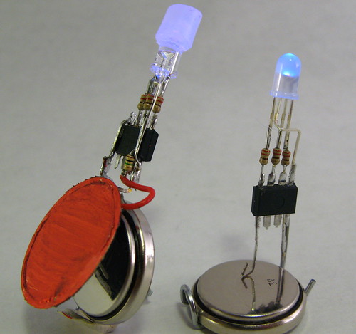
The circuits for the Smart LEDs on this page are essentially the same as Alex’s, except that an RGB LED is used instead. Electrically, an RGB LED looks like three LEDs. An Atmel AVR ATtiny13 is the microcontroller brain.
In this design the ATtiny13 is running at 4.8MHz from its internal oscillator with no clock scaling. That means it draws only about 1mA of current. The LEDs draw around 10mA for each color, so 30 mA total. But that’s a maximum, and by using PWM the average power consumption is a good deal less.
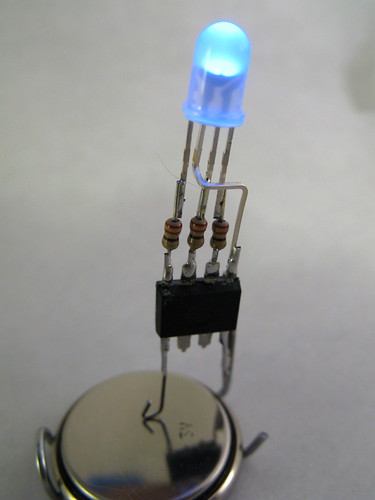
If you know how to program an Arduino, you can program one of these chips. The result is soldered together directly without the need of a PCB. Its only input is two power pins. Hook these pins up to any voltage between 2.7V and 5.5V to light it up.
The particular LED used for this Smart LED is a common anode one with a diffused lens. The common anode is connected to the positive power connection instead of ground, and all the on/off logic for the LED in the software must be flipped.
The software for this Smart LED is just a simple 3-channel software PWM color fade similar to Clay Shirky’s Arduino example.
Adding senses to the Smart LED
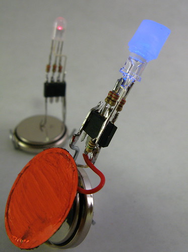
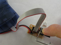
As with Alex’s Programmable LED, adding senses to a Smart LED is easy. Instead of a photocell, let’s add a piezo element ripped from an old buzzer and used as a knock sensor. Using piezos as knock sensors is easy. By soldering the piezo directly to the Smart LED, a nice little package is made.
The algorithm initially implemented for this Smart LED is a RGB color change like before, but if the piezo is struck, the LED turns white for a moment, then decaying down in brightness before returning back to the color changing.
In this case, a common-cathode RGB LED with crystal-clear lens was used with a small diffuser on top.
RGB LEDs and Diffusers
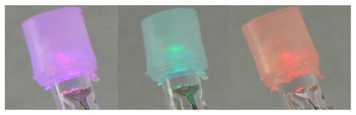
Most RGB LEDs you can find have a really narrow viewing angle, making them useful for flashlights maybe but not for ambient indicators. And because the red, green, and blue LED die are off axis from the integral lens that creates the narrow viewing angle, you don’t get very good color mixing. Sometimes you can find diffuse integral lenses on RGB LEDs (like the smaller smart LED pictured) but more often the lenses are crystal clear.
By placing a small dab of diffusive material on top of the LED, the light is mixed and diffused. In this case, a cylinder of unmelted hot glue was used:
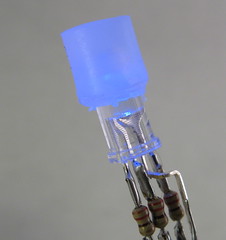
And then you can get a wide range nicely mixed colors:
Smart LED Prototype Programming
The fun part about building these devices is that you can reprogram them after you’ve constructed them. That is, if you’re careful and leave the back of the chips exposed. With the backs exposed you can press them only an 8-pin socket that is connected to a standard AVR ISP connector.
Smart LED Prototype Software
The software is really pretty easy stuff once you’re over the hurdle of AVR programming in general. As mentioned above, Arduino is a great place to start and you can review the Spooky Arduino class notes for a directed introduction.
After you know Arduino, it’s a small step to program AVR chips directly. You’ll need something like the AVRISP mkII programmer (about $35 from Digikey).
This particular software is kinda tricky because it implements software PWM. The software PWM code is directly borrowed from Atmel Application Note #136, “Low-Jitter Multi-Channel Software PWM” by Andy Gayne. I’ve successfully used the code to scale up to 16 software PWM channels and here, down to 3. At the 4.8MHz clock, the PWM rate is about 73Hz, which is low enough to cause beating with the 30 Hz rate of the video below. The PWM frequency could be increased with a few timer changes, but the rate isn’t visible to humans and any changes away from a known-working system should be avoided.
The software:
The code was quickly thrown together from another project, so the comments are either non-existent or misleading.
Smart LEDs Video Demo
Here’s a little demo of both of the Smart LEDs.
Hi Jason,
When working with LEDs, you always need resistors to go along with them, otherwise they’ll burn out by trying to draw too much power from the power source they’re hooked up to.
But once you have battery, resistor, and LED, you’ve got an LED flashlight. Your tri-color LEDs are really 3 LEDs in one package, so you’d need 3 resistors, one for each. Powering on all 3 of the LEDs inside the RGB LED makes it glow white, turning on or off just some of the 3 give you various colors.
If you google around, you’ll find lots of “LED tutorials” on the net. They’ll all give you similar information. I’m partial to the LED stuff in my “Spooky Arduino” class I gave last year. If you go to page 24 of the Class 1 notes you’ll get an intro into how to hook up LEDs with a 9V battery.
The value of the resistor you use determines how bright the LED gets. The lower the value, the brighter the LED. Up to a point. For your stuff, I would make sure all your resistors are 500 ohms and above. And I’d get several different values to play around with. If you’ve seen the “LED Throwies” on instructibles.com, you’ll notice they don’t use resistors; this is because the coin cells have a sort of built-in resistor.
Oh and if the only thing you want is white light, it will probably be easier to use white LEDs instead of the RGB LEDs.
Hello,
To start off I need to tell you that I know almost nothing when it come to technical electronics, but I love to play around with led lights. I have two tri-color leds identical to the ones in your pic’s… All I have are the lights and batteries… What do I need and how do I get a solid white beam out of the light ( I don’t need them to blink or flash ). Any help would be greatly appreciated.
…kewl stuff, good work further like this!
best regards
hoewe
Hello Todbot!
Love the Arduino tutorials! I have a question… I want to be able to develop my AVR apps using the Arduino board/software; then burn my sketches to offboard chips for use in projects like this smart LED.
I gather that I need the AVRISP USB programmer, but I’m PPC Mac based. What software can I use to upload/burn the sketch from my G5 iMac?
Yeah I figured the processes were different, especially for blue LEDs. But, as you say, since we have this nice large epoxy container, it should be possible to encapsulate a few LED dies and a microcontroller die in one 5mm resin package. Using bare die seems a fairly common practice now as most of the really cheap electronic gizmos wire up a logic die directly on a cheap circuit board and then plop a dab of epoxy over the entire thing.
I’ve looked at a few of these RGB LEDs under a magnifier, and they definitely look like different dies joined electrically, which made me wonder if the construction techniques for LEDs and cheap gizmos are really all that different.
The fab processes for these types of LEDs (GaN-based) and a microcontroller are actually very different because of the material properties. GaN circuits are still in their infancy because of problems growing quality wafers, and CMOS relies on high quality substrates plus silicon dioxide (the Oxide in CMOS) which you don’t get for free on GaN. I am guessing that the color changing LEDs have multiple die in one package for these reasons. Really not a problem since the size of a typical LED is HUGE compared to the actual light emitting device inside!
Hey, this is great — awesome. I think you’re definitely onto something here. Like, a lot of time and energy goes into doing something very simple that lots of people are trying to do with LEDs — everything from sourcing stand-alone PWM components to deciding which microcontroller to use based on whether it has enough PWM channels — can be taken care of with an LED that has such features built in already. I’d buy one for sure!
Hi todbot,
great! I like your smart LEDs. Nice idea to make it touchable. Maybe we should do a version that is able to listen?
And you solder better than I do. ;)
BTW: I have a new instructable, based on the same circuit. It simulates the synchronizing of fireflies: http://www.instructables.com/id/ETKA2PCF05JJP4O/
Kind regards,
Alex
neato!
Hi there,
thanks for that, much appreciated. WIll give it a go.
cheers
bert :-)
Hi Bert,
Using AVRISP over USB, programming takes just a one or two seconds. If it takes much longer than that, the “sclk” setting inside the AVRISP needs to be changed.
I’ve found the “C Programming for Microcontrollers” from SmileyMicros to be a good intro to AVR C programming. It’s based around the $20 AVR Butterfly board but the techniques are applicable for most all AVR chips.
If you’re familiar with Arduino, perhaps the best way to get into it is to use the Arduino board as just a carrier for the ATmega8 chip it has on it and reprogram it. Learning how the Arduino GUI does it’s job is very instructive. Check out the Arduino PinMapping, the BuildProcess, and how to program Arduino from the CommandLine.
From there it’s a small Makefile change to program the ATmega8 on the Arduino directly instead of using the Arduino bootloader. Burning your own code to the Arduino ATmega8 is just the same as burning the Arduino bootloader.
hi there,
thanks for that, do you have any good references or book to point me at to learn how to program C for the amtel family? At the moment I played around with programming ATTINY2313 using avrdude and a simple AVRISP (came with minipov) but am mainly just re-utilising the code that I’ve found. Would be nice to learn it rather than copying it. One thing I did find frustrating was testing, it took me so long to upload it to the chip then to see if it works. Thats why arduino was nice because it verifies your code and uploads it really quickly. any help much appreciated.
Out of interest how fast does it take to upload your file to the chip using the amtel AVRISP? and avrdude?
cheers bert
Yes, it’s all in C, and you compile the code from the command-line using a Makefile. The Arduino “language” is also C and the steps that the Arduino GUI goes through to build your sketches into executable code and program the board is almost exactly what the Makefile does. Arduino takes care of these details and the code to set the Arduino chip up, but otherwise it’s very similar.
A good way to start out is getting an AVRISP programmer and reprogramming the chip on the Arduino board without using Arduino. Once you’ve gotten the hang of that, you can move to different chips like this ATtiny13 which is very similar (but has much less memory, few I/O devices, etc.)
I’ve programmed arduino’s before but not sure how close this is to that enviroment? Does the code for these chips need to be programmed in C? when you say “If you know how to program an Arduino, you can program one of these chips. ” what do you mean? are they identical? any help much appreciated.
best
bert