LEDs should be smarter. Sure we have flashing LED assemblies and even rudimentary RGB-flashing discrete LEDs. But LEDs themselves are predominately just dumb lights. There’s no real reason for this. Fab processes for microcontrollers and LEDs aren’t that dissimilar. It should be possible to have both in a single LED-like package.
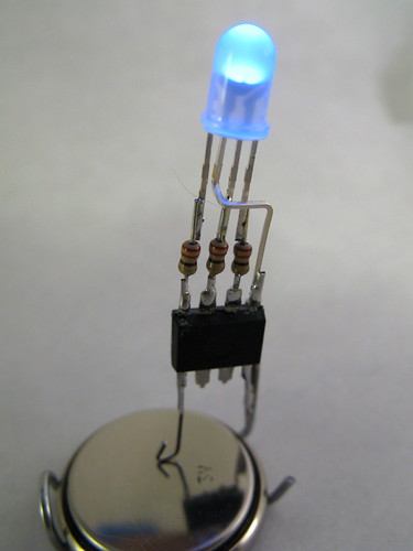
There is a glimmer of this happening, like the “RGB LED Slow Colour Change” LEDs you can get. You can see an example of these being used on the Embarrasingly Easy CaseMod. Unfortunately you can’t change the cycle time or anything else of how these LEDs work. So let’s make our own. These prototype Smart LEDs will necessarily be larger than a production run, but the size is getting close, giving us a feeling for how we might use them.
Smart LED Designs
Making a Smart LED just means adding a micrcontroller to an existing LED. Alex Weber created a neat version of this with his Programmable LED that has a blink pattern programmed by you via its integrated photocell.
The circuits for the Smart LEDs on this page are essentially the same as Alex’s, except that an RGB LED is used instead. Electrically, an RGB LED looks like three LEDs. An Atmel AVR ATtiny13 is the microcontroller brain.
In this design the ATtiny13 is running at 4.8MHz from its internal oscillator with no clock scaling. That means it draws only about 1mA of current. The LEDs draw around 10mA for each color, so 30 mA total. But that’s a maximum, and by using PWM the average power consumption is a good deal less.
If you know how to program an Arduino, you can program one of these chips. The result is soldered together directly without the need of a PCB. Its only input is two power pins. Hook these pins up to any voltage between 2.7V and 5.5V to light it up.
The particular LED used for this Smart LED is a common anode one with a diffused lens. The common anode is connected to the positive power connection instead of ground, and all the on/off logic for the LED in the software must be flipped.
The software for this Smart LED is just a simple 3-channel software PWM color fade similar to Clay Shirky’s Arduino example.
Adding senses to the Smart LED
As with Alex’s Programmable LED, adding senses to a Smart LED is easy. Instead of a photocell, let’s add a piezo element ripped from an old buzzer and used as a knock sensor. Using piezos as knock sensors is easy. By soldering the piezo directly to the Smart LED, a nice little package is made.
The algorithm initially implemented for this Smart LED is a RGB color change like before, but if the piezo is struck, the LED turns white for a moment, then decaying down in brightness before returning back to the color changing.
In this case, a common-cathode RGB LED with crystal-clear lens was used with a small diffuser on top.
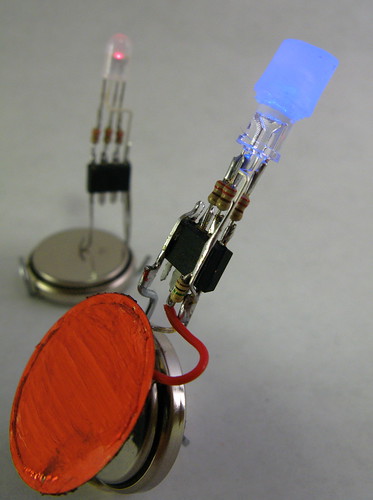
RGB LEDs and Diffusers
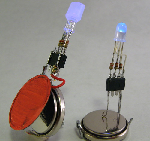
Most RGB LEDs you can find have a really narrow viewing angle, making them useful for flashlights maybe but not for ambient indicators. And because the red, green, and blue LED die are off axis from the integral lens that creates the narrow viewing angle, you don’t get very good color mixing. Sometimes you can find diffuse integral lenses on RGB LEDs (like the smaller smart LED pictured) but more often the lenses are crystal clear.
By placing a small dab of diffusive material on top of the LED, the light is mixed and diffused. In this case, a cylinder of unmelted hot glue was used:
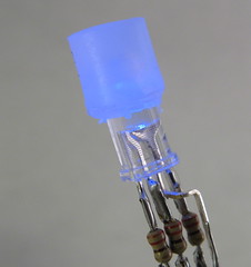
And then you can get a wide range nicely mixed colors:

Smart LED Prototype Programming
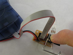
The fun part about building these devices is that you can reprogram them after you’ve constructed them. That is, if you’re careful and leave the back of the chips exposed. With the backs exposed you can press them only an 8-pin socket that is connected to a standard AVR ISP connector.
Smart LED Prototype Software
The software is really pretty easy stuff once you’re over the hurdle of AVR programming in general. As mentioned above, Arduino is a great place to start and you can review the Spooky Arduino class notes for a directed introduction.
After you know Arduino, it’s a small step to program AVR chips directly. You’ll need something like the AVRISP mkII programmer (about $35 from Digikey).
This particular software is kinda tricky because it implements software PWM. The software PWM code is directly borrowed from Atmel Application Note #136, “Low-Jitter Multi-Channel Software PWM” by Andy Gayne. I’ve successfully used the code to scale up to 16 software PWM channels and here, down to 3. At the 4.8MHz clock, the PWM rate is about 73Hz, which is low enough to cause beating with the 30 Hz rate of the video below. The PWM frequency could be increased with a few timer changes, but the rate isn’t visible to humans and any changes away from a known-working system should be avoided.
The software:
The code was quickly thrown together from another project, so the comments are either non-existent or misleading.
Smart LEDs Video Demo
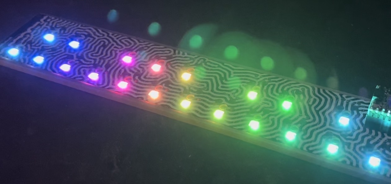
Here’s a little demo of both of the Smart LEDs.
Hi techiebot,
Every 8-bit AVR chip is programmable with the AVRISP, with the exception of the weird ones, like maybe the 6-pin ones. You can definitely program an ATtiny13.
But also, I wouldn’t be so quick to offload sensor reading tasks to an ATtiny if you’re using Arduino. I would try using just the Arduino first and see how far you can get. If you find you’re running out of cycles, at least you’ll have some working sensor-reading code that you can pretty quickly port to an ATtiny.
Todbot: I have been building robots for a while now. I want my current one the have smart sensors (IR sensor, accelerometer, light detector, touch sensors) and the like but I don’t want to use up the Arduino’s processing time looking at them all the time. Do you think the aTtiny13 would work for sensor input?
Octopart.com shows that there are many flavors of the aTtiny13. Would any of them work with the AVRISP programmer?
Thanks
I had more or less the same idea ~4 years ago, and came up with a similar circuit (used Tiny25, though in retrospect I could have gotten away with a Tiny13) for my RGB Christmas tree lights. Each light module has a linear power supply (with 50 feet of wire and wildly-varying loads, voltage drop would have been a major problem otherwise), Tiny25, resistor array (one for green, one for blue, and two in z-shaped series for red), a couple decoupling capacitors, and (of course) the RGB LED.
Take a look at my tree in action: http://www.youtube.com/watch?v=U5qR9_8KGPU
I know the first 34 seconds aren’t terribly impressive. Stick with it. It gets more exciting when the first chorus starts, and looks really cool at the song’s climax after the bridge as the final chorus starts.
PS if you run into anyone with the means to actually make smart LEDs, let me know… I’ve learned a lot over the past couple of years about what capabilities are really important, and what capabilities seemed like they’d be important, but ended up being irrelevant in real use on the tree ;-)
Hi Tim,
The mention of flicker makes me think that the fuses are set incorrectly, and the chip is running at 1/8th speed because the CLKDIV8 fuse is set. The flicker is maddening, right at the frequency to give one seizures it seems. ;)
In the Makefile above you’ll find a target called “erase” that will erase the chip and set the fuses correctly. So try doing a “make erase” then a “make program” (if you’re using the Makefile), or use whatever tools you have to flip the CLKDIV8 fuse.
Hi Todbot
I’m also getting a very noticeable flicker that gives you a headache if you look at it for too long. I’ve used the code that you provided with no modifications, I’m using avrdude with a parallel programmer. any ideas the chip is a attiny13v, thanks for any help you may be able to provide.
Tim
Awesome. thank you. setting the fuse was definitely the problem.
Hi Justin,
You probably need to set the CLKDIV8 fuse, which makes the chip operate at 8MHz instead of 1MHz. To do this with my code & Makefile linked above, do a “make erase” to set the fuses and then “make program” to reprogram the chip.
Hey Todbot,
Thanks for the great blog posts. I’m getting a really noticeable “flicker” when running the softpwm_t13.c. I’m not using a switch and was just trying to get smooth fading between colors on my common annode RGB LED. Is there anywhere in the code that you could point me to what I might be able to change to make the fading smoother?
I’m using a 4.5v power supply and everything seems to be working fine expect for the flicker.
Thanks for any directino
Hi piboer,
For the Smart LED prototypes, I got almost all my RGB LEDs from various suppliers on Ebay. Do a search for “rgb led” and you’ll find tons of different types. You generally have to buy in quantities of 25 or 50, but that’s still only around $20 total.
If you’re unsure what kind of RGB LEDs to get, check out Sparkfun, FunGizmos or similar purveyor of fine hacking components. One of the best things about these companies is they’re run by tinkerers just like us, stocking the parts they like the best. It means they’re a great filter for the daunting variety of electronic parts out there.
where did you get the RGB leds?
I’ve got these pieces of info from Wikipedia…hope it will help
# LEDs can emit light of an intended color without the use of color filters that traditional lighting methods require. This is more efficient and can lower initial costs.
# The solid package of the LED can be designed to focus its light. Incandescent and fluorescent sources often require an external reflector to collect light and direct it in a usable manner.
# When used in applications where dimming is required, LEDs do not change their color tint as the current passing through them is lowered, unlike incandescent lamps, which turn yellow.
Hi Gordon,
I’m not quite sure what you’re asking. Almost all RGB LED projects take three 8-bit numbers to set red,green, & blue, just like the three 8-bit numbers used to set an RGB on a display. Or are you asking how to physically mix the light? One uses some sort of a diffuser to do this usually. A diffuser is usually some sort of semi-transparent or frosted material, like white plastic.
Hi todbot
Do you know how to mix the color of RGB LED to match the color display on the computer? We want to design the display panel
-Gordon
Hi Jay, I have some of those RGB LEDs that (very crudely) color fade between red, green, and blue over about 5 seconds. They don’t blink though. I’d like to see a video of those LEDs you have, and a link on where to get them. :)
Todbot,
Thanks for the explanation I saw in the picture that you had the resistors on your leds, but wasn’t sure if I needed them to get the light to work (plus I don’t have any at the moment). Your response gave me great insight towards other questions that I had about types of resistors and such. Yes, you are also right it would be easier to just use a white light, and I have those, the reason behind the tri-color is because of the effect it produces when spinning or moving at high speeds. I also have some tri-color leds that I’ve come across that have a chip inside the light head that blends the colors in a fade mode (fading from one color to the other producing a rainbow effect) after about five seconds it switches to a blink mode. I’ve made a few toys out of these and it’s a trip to watch. Well, thanks again for the help and if you would like I could make a video clip of the leds I was referring too.
Jay