From Illustrator to Eagle: Vector graphics in circuits


Eagle is a great cross-platform, free-for-non-commercial-use tool for many of us designing our own circuit boards. But it has a pretty glaring omission: the ability to import vector artwork to use as board outlines, logos, etc. You can import bitmaps via the finicky “import_bmp.ulp” ULP add-on, but bitmaps can’t work for board outlines. So we struggle with Eagle’s rudimentary vector drawing tools or have boring rectangular or circular boards. I think I’ve found a way to robustly transfer vector artwork from Illustrator to Eagle. Below I show an “amoeba” vector shape in Illustrator being converted and used as a board outline in Eagle.

The short version of the steps are:
1. In Illustrator, add many extra anchor points
2. In Illustrator, export artwork as R13 DXF format
3. In Eagle, run the “import_dxf_polygons_v4.ulp” on the exported DXF file
4. Use resulting shape in your circuit

This is a fundamentally cross-platform technique: no special binaries needed, like some Windows-only DXF converters. Also, it should work for any other vector program that can export to a DXF format. And since the Eagle importer is public domain and freely inspectable, it can be improved over time. The importer is currently limited in many ways, but seems pretty usable, given appropriate input.

Step 1: Add Extra Anchor Points to Shape

The import command in Eagle produces only straight lines as output – any curves in your shape will be approximated by straight lines. To get around this, add extra anchor points/nodes to your shape. Add enough until you feel comfortable that the number of extra points sufficiently describes your shape. In Illustrator, this means running the “Add Anchor Points” repeatedly. You can find the command under the Object/Path menu:

Zoom into your shape when adding anchor points to see the points being added. Here’s a before-and-after of part of the amoeba shape:

If you don’t see the anchor points on your shape, be sure “Hide Edges” is turned off under the “View” menu.

Step 2: Export Shape as DXF

Illustrator supports exporting to DXF files natively. For importing into Eagle, we want the older R13 version of DXF. Here’s the settings I use in the DXF export dialog:

Be sure to place your shape as close to the lower left of the page in Illustrator, otherwise the shape will be far away from the origin in Eagle. (which is at the lower left)

Step 3: Import into Eagle

The DXF import is performed by the ULP “import_dxf_polygons_v4.ulp“. It is an updated version of the nice “import_dxf_polygons.ulp” extension written by Tim Ruetz and originally available from the Cadsoft Eagle userfiles misc area. I modified it slightly to let you select between WIRE (outline shape) and POLYGON (filled shape). Also, with WIRE, you can import unclosed objects, which you can’t do with POLYGON. Download the updated version here: “import_dxf_polygons_v4.ulp” and remember where you saved it.

In Eagle, from the Board window of your design, click the “ULP” button on the toolbar. Eagle will open up a “Run” file dialog. Navigate to where you downloaded the “import_dxf_polygons_v4.ulp” file and open it. You will be presented with a second file open dialog for “DXF file to import”. Navigate to your exported DXF file and open it. Then you’ll get the main import dialog:

From here you can rescale and mirror the shape if need be. The most important option is arguably the “Import to layer” one. For board outlines, use the settings:
– Layer: “Dimension”
– Type: WIRE
– Pen width: 0.0

When you click the “Execute” button, the shape will be placed into your board.

If you can’t see your shape, click the “Zoom Fit” button to fit all objects in the window. (the one to the right of the ULP button in the Zoom area of the toolbar) Now place your shape using a Group move.

Be careful using the POLYGON type. For shapes with interior holes, like the amoeba in this example, a POLYGON will fill in those holes, probably not what you want:

In most cases, use the WIRE type instead. It will also let you use open shapes like a spiral:

This isn’t useful for board outlines (which need to be closed), but could be useful for custom traces.

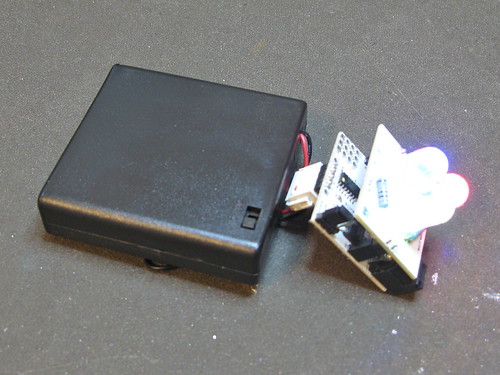
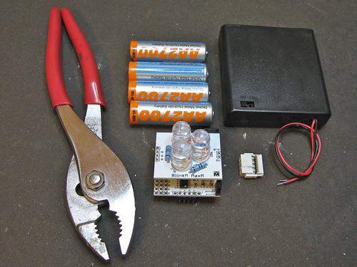
Let me know if you use this technique, or improve upon it. I think I’m going to try making this crazy little amoeba board that has an ATtiny on it, a bunch of LEDs, some I/O pins and a battery pack. :-)

(thanks to Carlyn for the inspiration and help in figuring this out, particularly in how to wrangle Illustrator)

BlinkM Cylon mkII

For Maker Faire this year I made a second version of my BlinkM Cylon: BlinkM Cylon mkII. This is not a very cost-effective way of getting a Cylon effect. It however is a good way of showing how to wire up multiple BlinkMs with a long cable, using our new WireM cabling kit for BlinkM. And unlike normal Cylon circuits, this has full RGB color effects and gradual fading.

BlinkM Cylon mkII

Here’s a quick video showing it in action.

BlinkM Cylon mkII consists of:
– 13 BlinkMs (one for each of the tribes of Kobol)
– one WireM cabling kit for BlinkM, consisting of IDC connectors and ribbon cable
– an Arduino
– two 4.7k resistors
– a single push-button
– 9VDC wall wart to power it all.
– laser cut acrylic enclosure

Below are all the files needed to recreate your own BlinkM Cylon. Click any of the images for larger versions.

Continue reading “BlinkM Cylon mkII”

NFC & RFID on Android, my Where2.0 2011 talk

I was invited to be a speaker at O’Reilly Where 2.0 Conference. It’s a conference mostly about mapping technologies, location-based services, and interesting new location-aware mobile apps.

I spoke about RFID and NFC, in the context of the release of the new NFC-capable Android phone, the Google Nexus S. Having an RFID reader in a phone could cause a big change in how we interact with the world around us. I talked about what RFID and NFC technologies are, how they work, some examples of them in the world and on Android, and how to add NFC capabilities to your Android app. And if the rumors of the new iPhone 5 are true, we’ll soon be awash in NFC applications.

My slides with notes: nfc_rfid_on_android_todekurt_where20.pdf (4.5MB PDF)

And here it is in slideshare:

Using FreeM with BlinkM MaxM

While FreeM is mostly designed to work with BlinkMs and MinMs, it can be made to work with MaxMs. FreeM cannot supply the power that MaxMs need (250mA and FreeM can only supply up to 100mA), but there are other ways. One way to do it is to power the FreeM from the MaxM’s built-in 5V power supply.

To do this, get a MaxM, a FreeM, a small scrap of wire, and a 12VDC power supply.

FreeM with MaxM

Remove the “pwrsel” jumper and wrap the small piece of wire around all three pins of the “pwrsel” jumper. Then plug the FreeM into the bottom of the MaxM and plug in the 12VDC power supply to the MaxM.

The MaxM will power the FreeM and the FreeM will control the MaxM.

FreeM with MaxM

You can also now control other LED clusters like flexible RGB LED tape.

FreeM with MaxM

BlinkM Battery Pack HowTo

BlinkM Battery Pack: Done!

Make a long-lasting, rechargeable battery pack for your BlinkM MaxM, BlinkM, or BlinkM MinM using just pliers, no soldering!

BlinkMs are perfect for portable, stand-alone uses. There are many ways to hook a BlinkM to battery sources. Here’s one way that works for all BlinkMs.

BlinkM Battery Pack: Step 1: Get all the parts together

BlinkM Battery Pack: Step 1: Get all the parts together

Parts are:

BlinkM MaxM, BlinkM, or BlinkM MinM

– 4xAA battery holder with switch, like this Jameco one or Mouser one

– 4xAA NiMH batteries (not alkaline!)

– 2×8 IDC crimp connector (FCI 71600-308LF), from Digikey 609-3570-ND or Mouser 649-71600-308LF

Tools you’ll need:
– pliers with wide jaws to crimp
– cutters to trim excess wire

Continue reading “BlinkM Battery Pack HowTo”

WiFi for Arduino with Asus WL-520gu

I love Arduino but its lack of wireless bugs me. And it sucks that WiFi Shields for the Arduino cost as much a cell phone. I want something cheap. Turns out, small, cheap WiFi routers like the Asus WL-520gu can run the DD-WRT Linux firmware and act as serial-to-network gateway for Arduinos (or most any other USB device). Here’s how to do it.

(Hey, is this a Wifi-controlled BlinkM? I think it is.)

A quick video showing a router acting as a serial-to-network gateway:

This is not that new of a concept, hacking Linux onto a router for some neat DIY purpose. One of my favorite past hacks is MightyOhm’s WiFi Radio project. And of course, see my own book Hacking Roomba for an example of how to put a Roomba on the Net.

This post is specifically about trying to make a DD-WRT router a transparent gateway for an Arduino.

The steps are:

  1. Install DD-WRT Firmware
  2. Configure Router to be WiFi Client
  3. Do Some Tests
  4. Install USB Serial Drivers
  5. Install Serial-to-Network Proxy

Continue reading “WiFi for Arduino with Asus WL-520gu”