Announcing blink(1) mk2, the USB RGB LED, improved

[cross-posted from the ThingM blog]

photo-main

We’re working on an improved version of blink(1) and have launched a Kickstarter for it.

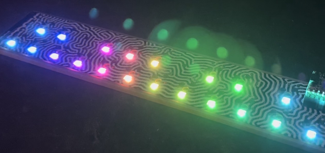
blink(1) mk2 is an updated version of the blink(1) super status light. The original blink(1) made it easy to connect any data source in the cloud or on your computer to a full-color RGB LED so you can know what’s happening without checking any windows, going to any websites or typing any commands. blink(1) mk2 maintains backward-compatibility while adding better functionality and great new features.

The main new features are:
– Better USB support
– Brighter via dual RGB LEDs
– Independently-addressable LEDs
– Improved Blink1Control application

We think it’s going to be great.
blink1mk2-ani

BlinkMuino updated for Arduino 1.0 (finally)

I finally got around to updating the BlinkMuino guide for turning your BlinkM, BlinkM MinM, or BlinkM MaxM into a tiny ATtiny85 or ATtiny84 Arduino system. BlinkM boards make great tiny development boards, especially if you’re interested in driving LEDs. BlinkM MaxMs are particularly great because they have more inputs and those three beefy MOSFET power transistors. And MinMs are good because they’re super tiny, but still contain a fully-programmable computer.

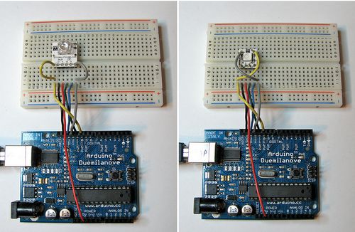
Thankfully, the ArduinoISP sketch has also been updated for Arduino-1.0, meaning you can use your Arduino as an AVR-ISP programmer, like this:

blinkmuino-arduino-500px

Here’s the original video I made about BlinkMuino:

We’ll be showing off some examples of BlinkMs programmed with Arduino at Maker Faire, some say “hi”!

Arduino-serial: updated!

In late 2006 I wrote “arduino-serial“, mostly for myself, to help with stuff I was working on at the time. It was a very simple & small, cross-platform tool written in basic C for reading/writing serial ports.

Now nearly seven years later I still get regular questions and frustrations about it. Part of this is due to how Arduinos have changed over time. You used to have to hand-reset an Arduino board, now the act of opening the serial port resets it. This has its plusses and minuses, but it really made my original use-case of arduino-serial fail. Then there were just all the minor deficiencies of the program.

To address some of these issues, but still keep things small & light, I’ve done a bit of fix-up of arduino-serial. It’s now hosted on Github at:
https://github.com/todbot/arduino-serial/

Changes & Improvements

Some changes that I recently made to arduino-serial:

  • Separation of the application (arduino-serial.c) from the library (arduino-serial-lib.{c,h})
  • Fixed probable --read bug
  • Fixed --port open to allow re-opens
  • Added --sendline command to send a string followed by a newline
  • Added --flush command to clear out receive buffer
  • Added --eolchar option to let you specify your own end-of-line character if ‘\n’ isn’t appropriate
  • Added --timeout option to specify a read timeout (reads no longer block infinitely)
  • Added --quiet flag to make output more terse/machine-readable

Here’s what the new usage help screen looks like:

laptop% ./arduino-serial
Usage: arduino-serial -b <bps> -p <serialport> [OPTIONS]

Options:
  -h, --help                 Print this help message
  -b, --baud=baudrate        Baudrate (bps) of Arduino (default 9600)
  -p, --port=serialport      Serial port Arduino is connected to
  -s, --send=string          Send string to Arduino
  -S, --sendline=string      Send string with newline to Arduino
  -r, --receive              Receive string from Arduino & print it out
  -n  --num=num              Send a number as a single byte
  -F  --flush                Flush serial port buffers for fresh reading
  -d  --delay=millis         Delay for specified milliseconds
  -e  --eolchar=char         Specify EOL char for reads (default '\n')
  -t  --timeout=millis       Timeout for reads in millisecs (default 5000)
  -q  --quiet                Don't print out as much info

Note: Order is important. Set '-b' baudrate before opening port'-p'.
      Used to make series of actions: '-d 2000 -s hello -d 100 -r'
      means 'wait 2secs, send 'hello', wait 100msec, get reply'

Using arduino-serial

arduino-serial has always been designed so you can “pipeline” commands/options, but it wasn’t implemented very consistently. It’s a bit better now. You can do multiple send/read pairs, even use multiple serial ports, all from a single command-line invocation.

For example, if you have the “SerialCallResponseASCII” sketch from the Communications examples loaded onto your Arduino, you can run commands to take multiple data readings. In the example below, the order of operations are:

  1. serial port is opened (at 9600)
  2. the string “A” is sent (a single-byte)
  3. the first line is read
  4. sleep for 1000 milliseconds
  5. send “A” again
  6. read second data line
  7. flush read buffer (just to show we can)
  8. send “A” a third time
  9. and take a final reading
laptop% ./arduino-serial -b 9600 -p /dev/tty.usbmodemfd131 \
            -s "A" -r  -d 1000  -s "A" -r  -F  -s "A" -r
send string:A
read string:465,396,0

sleep 1000 millisecs
send string:A
read string:358,352,0

flushing receive buffer
send string:A
read string:307,305,0

The flush was put in there to demonstrate that you could flush the receive buffer mid-command if you wanted. It’s not required, but might help some situations.

To use multiple serial ports, you can do something like the below, which opens up one serial port at 9600 bps, does a send & receive, then opens another at 57600 bps and does a send & receive on it:

laptop% ./arduino-serial -b 9600 -p /dev/tty.usbmodemfd131 \
        -s "A" -r \
        -b 57600 -p /dev/tty.usbserial-A800f8ib \
        -s "hello" -r 

BlinkM Coin Cell Holder

BlinkM coin cell holder

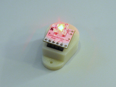
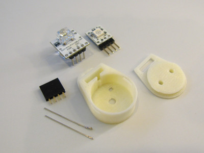
Did you know you can power BlinkMs or BlinkM MinMs off two 3V coin cells? Here is a tiny 3d-printable coin cell and header socket holder for BlinkMs and BlinkM MinMs. It snaps together and has mounting holes to turn it into a pendant or mounting additional diffusors for the LEDs.

And you don’t need many parts to build it:
– one each of plastic pieces here (see the STL files on Thingiverse)
– two CR2032 3V coin cells
– one 4-pos female header socket (Digikey S7037-ND or equivalent)
– two short pieces of solid wire (old resistor leads, 26 gauge wire stripped, etc.)

BlinkM coin cell holder

Steps:
1. Push the 4-pin socket into the hole until it stops. It should friction-fit in without any need for glue.
2. On the bottom, feed the two wire pieces in as shown in the photos, and solder them to the two pins on the header socket. These wires become the battery terminals.
3. Bend the wire battery terminals so they make good contact with the cells.
4. Insert coin cells, snap together top piece.
5. Insert BlinkM and watch it play its light sequence.
6. To protect the back, put a small piece of gaffers tape or similar over the terminals.

For more info and pix, see this project’s Thingiverse page or the Flickr pictures.

listComPorts – Windows command-line tool for USB-to-serial

Did you know each Arduino has a unique serial number in its USB interface that you can use to distinguish one Arduino from another? If you deal with multiple Arduinos, knowing exactly which one is plugged into your computer can be a real time-saver. But actually getting at this serial number and mapping it to COM ports can be challenging.

For Windows computers, here’s “listComPorts”, implemented both in GCC C code and in VBScript, both available from my usbSearch github repository.
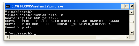
It gives the COM port number, the manufacturer name, the USB Vendor ID and Product ID (VID & PID) and the serial number. The result is a concatenation of the VID, PID, and serial number that Windows calls a “PnPDeviceID”. You can use the whole thing, or pick off the parts you need using simple string processing libraries. In the example above, the Arduino Diecimila has a VID/PID pair of 0403/6001 and the Teensy has a VID/PID of 16C0/0483.

Arduino Serial Numbers

In the above example, the Arduino Diecimila (which has an FTDI chip) has the serial number with a “+”-sign after the PID. So, the serial number is “A6004CCF”. The Teensy can have a programmable serial number and by default it’s set to “12345”.

With Arduino UNOs and future Arduinos, the Arduino team has their own VID/PID pair, which let’s them assign different PIDs for different classes of Arduinos. The UNO also has a much longer unique serial number than older Arduinos using the FTDI chip.

Here’s an example with two Arduino UNOs:

The serial numbers are separated by the VID/PID pair with a backslash. So my two UNOs have the serial numbers “64936333936351408161” and “6493234373835191F1F1”. Using this info, I can be sure exactly which Arduino I’m dealing with.

How it works

The C and the VBS versions both utilize the WMI infrastructure that’s been around since Windows 2000 to query the machine about its configured PnP devices. The WMI is a huge data structure of just about any information in Windows. Except, it seems, good information about COM ports. While there is a “Win32_SerialPort” table in WMI, that only contains information about hardware serial ports, not USB-to-serial adapters. Instead, these two tools look at the “Win32_PnPEntity” table. While this table does list USB-to-serial adapters, it does not contain a proper mapping of the adapter’s USB or PnP ID to COM port. Instead, these tools do a string search on the “Caption” field for the string “(COMn)” where “n” is a number. It’s an incredible hack but seems to work.

Other operating systems

On Mac OS X and pre-UNO Arduinos, knowing exactly which Arduino you were dealing with was easy because the FTDI driver put its serial number as part of the name of the serial port. For example, the port name created by the FTDI driver was “/dev/tty.usbserial-A6004ccf” and the serial number was “A6004ccf”.

With the UNO, the Arduino team used a reprogrammable ATmega8/16u USB chip using standard CDC USB-to-serial interface, which all OSes support natively. Unfortunately, on Mac OS X, the OS’s CDC driver creates a serial port for the UNO based on USB port location, not Arduino serial number.

Thus where you plug in the UNO into determines its serial port name. For instance, on my Mac, plugging in an UNO with serial number “64936333936351408161” gives a serial port with the name of either “/dev/tty.usbmodemfd131” or “/dev/tty.usbmodemfa141” depending on which USB jack is used. Even if you plug in a different UNO in the same jack, you’ll get the same serial port name. This is useful for some applications, but not if you need to know exactly which UNO you’re dealing with.

For Mac OS X, I use a tool I wrote called listArduinos.pl. It tries to determine the serial port names of every Arduino Uno. It’s out looks like:

bokbok% ./listArduinos.pl         
Finding Arduino UNOs...
/dev/tty.usbmodemfd131 - 0x2341/0x0001 - 6493234373835191F1F1
/dev/tty.usbmodemfa141 - 0x2341/0x0001 - 64936333936351400000
Found 2 Arduino UNOs
bokbok% 
Invisible Accent Light with BlinkM MaxM & FreeM

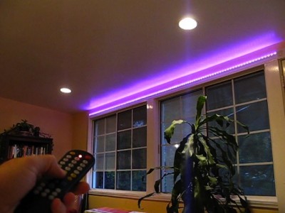
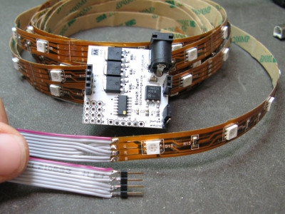
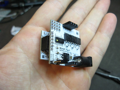
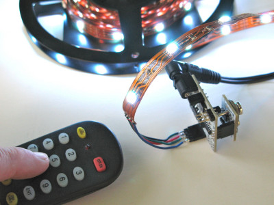
Sometimes you just want a little extra light in a room. With RGB LED tape, you can put light anywhere. But controlling its brightness and making it the color you want is a bit harder. A BlinkM MaxM can easily control LED tape, either as a stand-alone device, with an Arduino, or your computer via a LinkM. Stand-alone mode is great if you want a specific color or color pattern (the BlinkMSequencer makes this really easy) For this installation, I added a FreeM to the MaxM to let you control the light with a standard infrared TV remote control.

Accent Light with BlinkM MaxM & FreeM

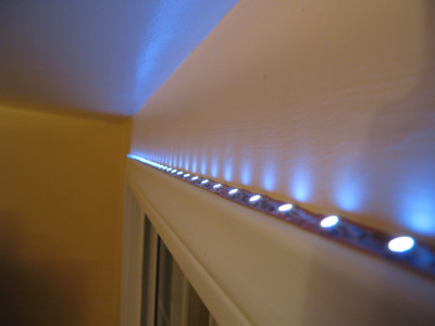
Another nice thing about the LED tape is that when it’s off, you can’t see where it’s installed.
Here’s a video showing how it all works.

How to make this

The parts you’ll need are:
BlinkM MaxM
FreeM
RGB LED flexible tape
12V DC @ 1A power supply, you probably have this laying around
– Any universal TV remote, like this one

First up is to wire up the RGB LED tape with extension wires to go from the tape to the MaxM. This is so you can hide the MaxM where ever you feel like. Cut the wires to the length you need and solder them to the LED tape and a 4-pin male header like in the photo below. Note because the LED tape switches the Red and Green lines you’ll need to switch them because MaxM’s lines go V+,R,G,B.

Accent light with BlinkM MaxM FreeM

With that done, you should be able to hook everything up and have the MaxM drive the LED tape. The LED tape takes +12VDC. The amount of current it needs depends on the length of tape your driving. Chances are you have a 12VDC @ 1000 mA wall wart power supply from an old piece of computer gear. That should work fine.

If you want your accent light to play a constant color or color pattern, you’re now done and can place the LED tape where ever you like, like on top of a window sill. Peel off the sticker backing and stick the LED tape where it should go.
Accent light with BlinkM MaxM FreeM

Adding FreeM

If you want to go the step further and add a FreeM to give your light a remote control, then follow the steps on the Using FreeM with BlinkM MaxM page.

But it’s really not much more than plugging the FreeM into the bottom of the MaxM.

Accent light with BlinkM MaxM FreeM
FreeM with MaxM

I’m a video star on Slate, sort of

SlateV had a feature on 3D printing and Makerbots entitled “How to Print a Bicycle”. Bre of course was the spokesman. About halfway through it though, my friend Jon saw my face. Whoop, I’m famous! Okay, so maybe not famous exactly. But they did feature one of my creations (at the 3:15 mark).

While I think it’s cool they used my laser-cut iPhone stand as the representative of what Thingiverse is about, they probably should have used something 3d printed instead of laser cut. :)