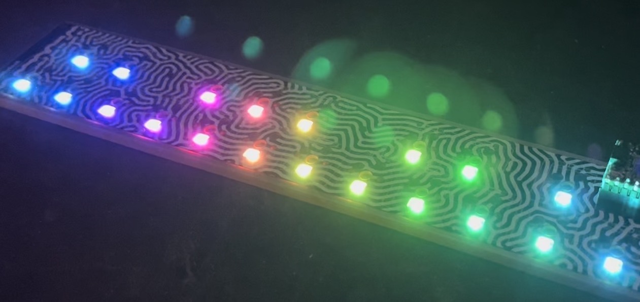
Bionic Arduino is a set of four 3-hour classes in November 2007 hosted by Machine Project and taught by Tod E. Kurt. It is an introduction to microcontroller programming and interfacing with the real world using the Arduino physical computing platform. It focuses on building new physical senses and making motion with the building blocks of robotics, using Arduino as a platform.
In the class, participants are shown and experiment with the Arduino’s capabilities and learn the basics of common microcontroller interfacing, such as: digital output to control lights and LEDs, digital input to read switches and buttons, analog output to control motor position or LED brightness, and analog input to read sensor inputs.
The class assumes no previous electronics knowledge, though it does assume a little programming knowledge. No soldering is needed during the class, as all circuits are built with solderless breadboards.
Class Notes
- bionic_arduino_class1.pdf (7.7MB PDF)
- bionic_arduino_class2.pdf (9.2MB PDF)
- bionic_arduino_class3.pdf (4.9MB PDF)
- bionic_arduino_class4.pdf (6.6MB PDF)
Arduino Sketches Used in Class
- Blink – Blink an LED
- Fading – Vary the brightness of an LED
- FadeOrBlink – A button to switch between Fade or Blink
- CandleLight – Random behavior emulates candles
- PotDimmer – Use a pot to change brightness
- RGBMoodLight – Control RGB LED algorithmically
- RGBPotMixer – Control RGB LED with a pot
- SerialHelloWorld – Say hello to serial
- SerialReadBasic – How to read serial values
- SerialReadBlink – Change blink rate with serial commands
- SerialRGBLED – Change LED color with serial commands
- SoundSerial – Use serial input to control piezo buzzer
- PlayMelody – Play a pre-defined melody
- Theremin – Use a photocell & piezo as a theremin
- SerialMotorSpeed – Control motor speed over serial
- PiezoKnock – Make a piezo buzzer a sensor
- PiezoMotorPulse – Turn on a motor if knocked
- PotSend – Send binary pot data (for Processing)
- ServoSimple – Move a servo back and forth
- ServoSerialSimple – Control servo from serial port
- ServoSerialBetter – A better way to control a servo
- NunchuckPrint – Print sensor data from Wii Nunchuck
- NunchuckServo – Use Nunchuck to control a servo
- bionicarduino-sketches.zip – All Arduino sketches zipped up
Processing Sketches Used in Class
- ArduinoReadCircle – Circle sizes changes from Arduino knob
- ArduinoBounce – Ball size changes from Arduino knob
- ArduinoSounds – Trigger sounds from Arduino knock sensor
- bionic-processing-sketches.zip – All Processing sketches zipped up
Parts Suppliers, New
- SparkFun — Arudino board and shield, and many other neat gizmos.
- Jameco — General electronic parts, easy-to-use, also has computer parts.
- Digikey — Exhaustive parts supplier. Cheaper than Jameco usually, has more variation, more hard-to-find parts.

Hi Richard,
The port name will be the same as the one you use with Arduino, under the “Tools -> Serial Port” menu. The exact value will be different for every Arduino.
(You can use this fact to distinguish between multiple connected Arduinos and have them do different things. For instance, I have one Arduino that is “/dev/tty.usbserial-A4001lZf” and another Arduino that is “/dev/tty.usbserial-A7006xIM”)
Hi Tod… thanks for the awesome site. I’m having trouble getting Processing to connect with my Arduino board. Specifically with the ArduinoPong sketch. I close all Arduino applications and have only the ArduinoPong sketch window open but it receives no input. I am certain that my board is transmitting with the PotSend sketch. I am using port10. I use: “/dev/tty.usbserial-A4001qa10” as the port name. Any help appreciated. Thanks in advance.
Hehe, well Mik, if you put no restrictions on it like that, then the answer is basically: “as many as you want”.
When controlling LEDs there are usually two things you have to worry about:
– power draw — how much current needed for your LED array
– addressing — how to control a specific LED in your array
By saying external power source, you get around the power draw issues. An Arduino on a USB port can supply about 500mA of current. A standard LED draws max about 20mA of current. So you can have 500/20 = 25 LEDs off a single USB-powered Arduino. Of course, the Arduino chip itself can’t supply enough power directly to do all 25, you’d need some external driver transistors to help out. Or use LED driver chips.
As for addressing, an Arduino has 13 digital I/O pins. If you set those up as a matrix of 6 pins by 7 pins, you could address 42 LEDs with just the Arduino. But since you include LED driver chips and shift registers in the mix, those chips can do all the hard work and you just talk to them via multi-node serial protocols like I2C or SPI. There are LED driver chips which can address 24 LEDs at a time and are meant to be bussed together in a long string. So you could have maybe 100 of these chips and be able to have 240 individually-addressable LEDs.
But now you have to start worrying about logical addressing. If you think about what an Arduino program to control a few hundred LEDs would look like, you’d probably have a big array in memory, with each array byte is the brightness value of one LED. (many call it a “framebuffer” after what video cards do) A standard Arduino has 1024 bytes of RAM, of which about 256 bytes of this is used by various libraries like Serial. Your program’s non-framebuffer variables take up some of that too. So let’s just say that you have 512 bytes of RAM free for your framebuffer. That means 512 LEDs is your maximum.
Of course, if you don’t need to remember the value for each and every LED (like if you’re doing algorithmic stuff where a “next” LED value can be computed by a small number of “previous” LED values), then your memory requirements can be much smaller than one-byte-per-LED.
If you’re asking your question for more then theoretical curiosity, like say for a particular application, it might be better to say what you’re trying to do. Like most things in technology, there are many options, so the problem needs to be defined better so a solution can be properly fitted to it.
To be more specific I’d like to know the maximum possible amount of controlled LED’s from a Duemillanove with use of any trickery :) including shift registers, charlieplexing or any other chips. Cheers
Hiya Tod, love the site
I’ve been playing around with MAX7219’s and an Arduino Duemillanove, I’m wondering if you can tell me the theoretical limit of how many non-rgb Leds the arduino can control individually (with an external power source if need be).
Thanks
Mik
Tod:
This time you were right – the XBee adapter from Adafruit was easy to make and get working. There was really no need to stack an XBee shield on a motor shield. We used 4 wires from the XBee adapter right to the motor shield. We also used Limor’s tip to use the analog ports for digital ports 14-19 which worked out nice. We posted some details on http://sports4nerds.blogspot.com/.
Ps – now we have new problems – the h-bridge on the motor shield is not providing full power to our DC motors and overheating. We are going to try stacking another h-bridge or find another that can handle more amps.
Thanks again for your help.
Jules
Hi Jules, Ahh you’re right. Looking a bit closer, it appears that the motor shield and the most all Xbee adapters I looked at aren’t able to be stacked. This is unfortunate. You should send an email to Adafruit mentioning this problem. All the different Xbee adapters I looked at use the 6-pin ICSP pins, which is sorta oddball: most shields don’t need use that.
What you should be able to do, but it’s not as compact, is to use Adafruit’s Xbee Adapter Kit plugged into a solderless breadboard. See the bottom of the XBee adapter Arduino page for how to hook it up to an Arduino. (be sure to solder in straight headers instead of the right-angle ones)
Tod: Please help. We got our first Arduino, Adafruit’s motor shield kit and Xbees with Xbee adapter from NKC. When I look at this http://www.ladyada.net/make/mshield/solder.html We dont see how the motor shield and Xbee will work together with this Xbee shield: http://www.nkcelectronics.com/xbee-shield-remixed.html (from http://www.seeedstudio.com/depot/xbee%C3%82%C2%AE-shield-remixed-p-227.html) Thanks for your help. Jules ps: we got blink working and you would think we placed a man on the moon we were so happy.
Hi Jules,
What makes you say that the Xbee and motor shield won’t work together? I think you should be able to use an Xbee shield or Adafruit’s Xbee adapter with an Arduino motor shield.
If you’re concerned about how to connect multiple shields to an Arduino, the current standard practice is to stack Arduino shields on top of one another. Many shields come with “stacking headers” to enable this. Or you can get a stacking header kit from Adafruit or a stacking header kit from NKC Electronics. NKC also carries Xbee shield kits, in case you want to save some money on Xbee and like to solder.
Needless to say great tutorials – I am building a 6-wheel bot with my dad that needs to be remote (wireless) controlled. We wanted to use Xbees and the Adafruit motor shield (for 2 motors variable speed – forward and reverse) but they don’t seem to work together. We looked at double-wide boards but we are not sure they will work and we are not getting a reply to out emails (and the bluetooth Arduino is too costly). Do you have a suggestion for what we can use for wireless communication from a PC, or how we can get motor shields and Xbee together on a Arduino? Thanks in advance – Jules