
There’s been some confusion as to whether or not the DIY RGB orb presented in the last post was actually connected to a computer and receving color data from it. Here’s a video that more accurately depicts what’s going on and all the code used to create it.
Hardware
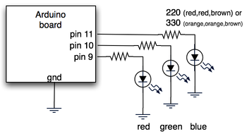
The hardware is just an Arduino board connected via USB to a laptop. The Arduino appears as a serial device to the computer. On the Arduino board, three LEDs (red,green,blue) are mounted directly to the Arduino board using a prototyping shield like this DIY one. The schematic is quite simple:
Arduino code
The code sketch running on the Arduino board is a slightly modified version of the one presented in the last Spooky Arduino class. Instead of parsing single color values over the serial port, it expects a full RGB color value in standard web format of “#RRGGBB” (white is “#ffffff”, blue is “#0000ff”, and so on). The sketch parses that seven character string into three bytes: one each for the brightness values of the red, green and blue LEDs.
Arduino code: serial_rgb_led_too.pde
Processing code
To bridge between the Arduino and the Net, a small Processing sketch was created that uses the standard Java HTTPURLConnection class to fetch a web page (really, a text file on a web server) containing a line with a color value in the format “#RRGGBB”. The sketch parses the color value, sends the value out to the Arduino orb using the Processing Serial library, and then sets its own background color to match. Because I’ve set the framerate of the sketch to 1 fps, it takes a second for the background to match the orb. I did this on purpose so I could get a sense of the color as the orb reproduces it before seeing it as it truly is. I was surprised how well the two tended to match!
Processing code: http_rgb_led.pde


 NicePlayer
 Perian