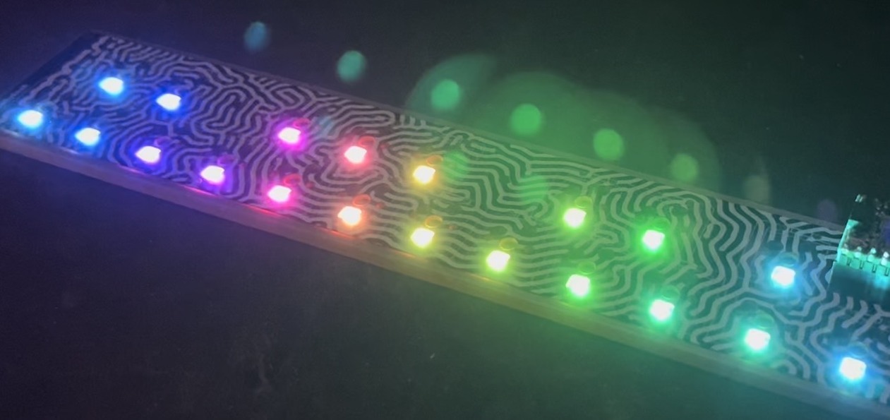
BlinkM MaxMs will be back in stock soon. Over on our GetSatisfaction area, there’s a question on how to use multiple BlinkM MaxM “Blaster” LED boards with one MaxM “Master” driver board. It’s possible and only just a little tricky. The Blaster board is powered by the 5V voltage regulator built-in to the Master board. That regulator is designed to power just one Master and one Blaster. If you try to drive multiple Blasters with it, it might work, but we don’t recommended it and could blow up your Master board.
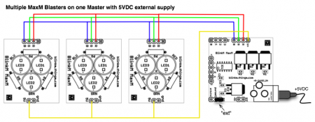
Instead, it’s better to drive the MaxM with an external 5VDC power supply. This isn’t officially within the operating range of input voltage for the Master, but for this application it’s okay. To drive multiple Blasters, you then run that external 5VDC supply, available from the “V+” socket to the “5V” pin of each Blaster. And do not connect the Master’s “5V” to anything. Here’s a wiring diagram (click to enlarge):
There are a variety of ways o wire this up. I really like the 2×4 IDC connectors, as I described in the “BlinkM Cylon” post. They’re almost like little 8-pin breadboards. For this application, the one connector will carry both the V+,R,G,B signals coming out of the Master, as well as providing 5V to the “5V” pin of each Blaster. But because the spacing of the pins in the Blasters are too far apart to use just one connector, two connectors are used per Blaster: one for the V+,R,G,B side and one for the 5V,Gnd side.
When I wired this up, I made the “left” row of four pins in the connector be used for the 5V,Gnd pins of the Blaster. Plug the 2-pin 5V/Gnd connector of each Blaster into that. On another connector, I had the the “right” row of four pins act as the V+,R,G,B pin, so plug the 4-pin connector of the Blaster into that. To make “V+” from the Master act like “5V” to the Blasters, run a small jumper wire beteween “V+” and “5V” on another connector. Finally, plug the V+,R,G,B side of the last connector into the V+,R,G,B socket on the Master. Be sure to get the orientation right! It gets confusing fast. Here’s a picture of my wiring job (click to enlarge and go to the Flickr page with notations):


Yeah, power concerns start to add up quick once you start doing real stuff. You can drive the Arduino from an external regulated 5VDC source, just wire it into Arduino’s 5V & Gnd pins and ignore the DC barrel connector.
There are some nice 5VDC regulated wall warts that supply 1A or more. You may have one already from an old WiFi router or MP3 player charger. If not, you can find them on the net really cheap. For instance, here’s a 1.2A one for $5.34 from Monoprice. It’s got the tiny barrel plug on it, but that’s okay because you’d have to cut it off like the plug of any other 5V power adapter so you can have wires to stick into the 5V & Gnd sockets on the Arduino board.
Thanks for this!
I think that given what you have said I had better stick with a separate supply. I am also going to be driving 2 servos as well as the 2 blaster boards and I definitely don’t want to fry my Arduino!
Thanks again
Chris
Hi Chris,
Yes, you can do that, but you run the risk of overdriving the power supply of the Arduino if running stand-alone or drawing too much current from USB, if connected to USB.
This is because both the Arduino and USB can only supply 500mA of current and each Blaster when full on draws 250mA.
The USB specs state that if you draw more than 500mA from a port, the port will get turned off so it doesn’t short out your computer. But if you’re running your Arduino stand-alone there’s no such protection, so monitor the Arduino’s power area to make sure it doesn’t get too hot.
If you want to try this and promise yourself not to turn the Blaster full-on, then want to connect the common “5V” connection of each Blaster to the “5V” connector on the MaxM or Arduino.
Hi Todd
I was looking to drive 2 blaster boards from 1 MaxM connected to an Arduino, but had hoped to not use a separate power supply.
Is there is a similar configuration driven directly from the Arduino rather than using a separate 5V supply?
I’m afraid I am new to all of this, so this may be a bit of a stupid question. Any help you could provide would be much appreciated.
Thanks in Advance
Chris
Hi Patrick,
The pull-up voltages just need to be referenced to the common GND connection, so you can use the Arduino 5V supply just fine. That is, you’re doing things exactly right. :)
Very useful post. Does exactly what I need.
Just one question: when using long ribbon cables for I2C control of this setup where would my pull-up resistors go in the circuit?
I’m finding that without pull-up resistors, I’m getting no response when connecting two sets of Master + 4 Blasters. I’m using ribbon cable for the I2C, as in this post, both cables are 105″ long. Connecting just one works fine, but connecting both I lose control.
I’ve tried putting a resistor between both the SDL and SDC lines and the Arduino’s 5v pin (2.2kohm resistors seem to work in my setup).
That seems like it works. But as we’re not otherwise using the Arduino’s 5v in this configuration (just GND, pin 4 and 5 for the I2C connection) I wasn’t sure if there was a different way I should be doing this.
Hey todd.
Very cool stuff.. I was looking for your email but didnt find it? Can you drop me an email I had a few questions about your USB on Rails talk.
Thanks!
Rileyporter [at] gmail.com