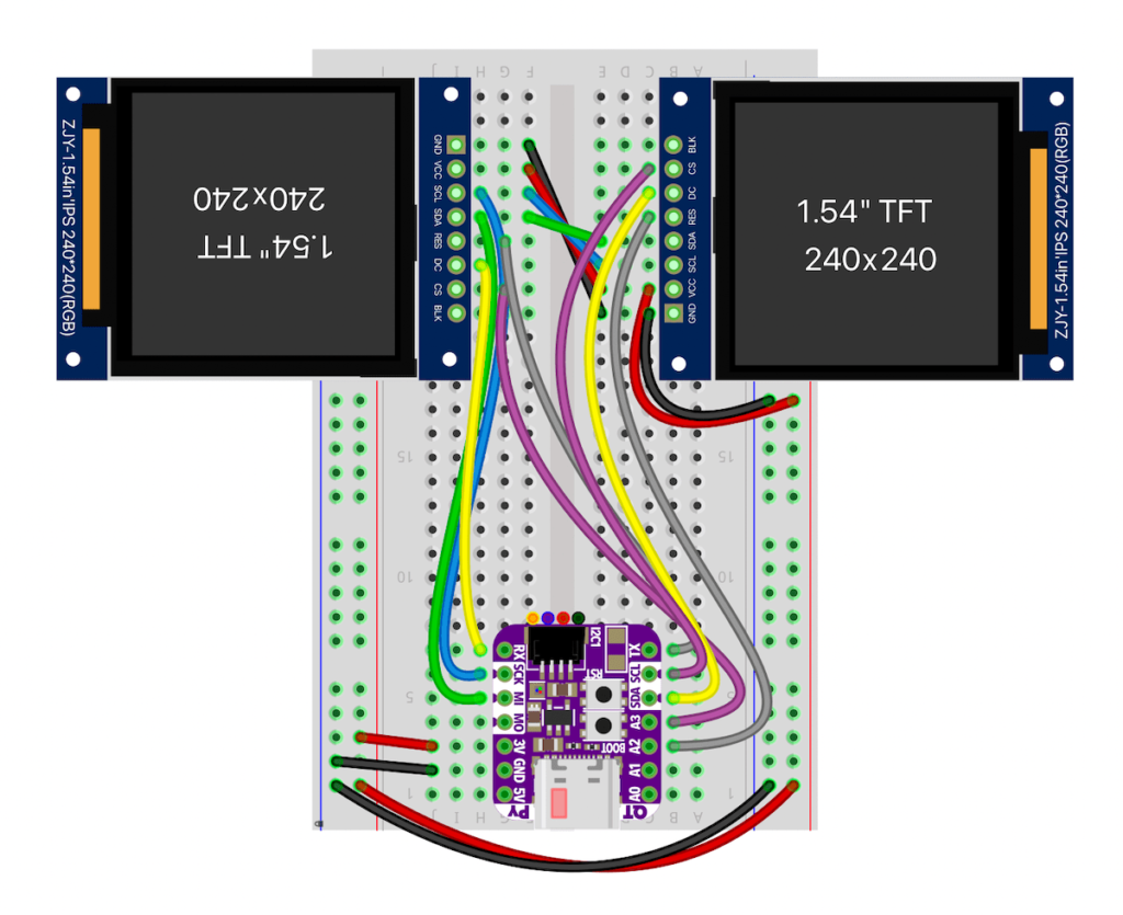
Did you know you can run multiple displays in CircuitPython? One way: wire up two displays in parallel.
There’s also true dual displays, more on that in a bit. For the above, here’s the wiring diagram and the code “gc9a01_hellocircles_compact.py”. Note how the second display is hooked up in parallel and the code just sees one display.
But what if you want each display to be independent?
Almost all CircuitPython boards support a display. CircuitPython makes it really easy to configure a display’s driver and all displays act the same for drawing images and text: monochrome OLEDs, RGB TFT LCDs, even ePaper!
But only a single display is supported for the pre-built versions of CircuitPython (The one exception is the MonsterMask) Multiple displays are supported in the design of CircuitPython, but it’s a compile-time setting. This is for RAM savings reasons. That decision is a few years old and I think for modern chips like ESP32-S2/3 and RP2040, there’s more than enough RAM to allow that default to go up to two.
Compiling CircuitPython to Add Second Display
In the meantime, we can re-compile CircuitPython ourselves to increase that limit. It’s pretty easy if you’re comfortable with the command line. If you’re already know how to build CircuitPython, the short answer is:
Add this line to your board’s mpconfigboard.h:
#define CIRCUITPY_DISPLAY_LIMIT (2)
recompile and install the resulting UF2 file.
If you’ve never compiled CircuitPython before, there is a very useful Adafruit Learn Guide building CircuitPython. I recommend start there and go through each step. This post is not that. This post is a reminder for myself, with an abbreviated version those steps that I can just copy-n-paste when I want an entirely fresh checkout. Not all of these steps are needed if you already have a checkout.
First: initial git checkout, getting the git submodules, and installing python requirements.
git clone https://github.com/adafruit/circuitpython circuitpython-todbot
cd circuitpython-todbot
make fetch-submodules
git checkout main
pip3 install --upgrade -r requirements-dev.txt
pip3 install --upgrade -r requirements-doc.txt
make -C mpy-cross
Next: do an easy build for QTPy M0 to make sure everything works:
cd ports/atmel-samd
make BOARD=qtpy_m0
# or can do: make -j10 BOARD=qtpy_m0   # since you have lots of cores
ls -l build-qtpy_m0/firmware.uf2
Also, let’s try building CircuitPython for Raspberry Pi Pico:
cd ports/raspberrypi
make -j10 BOARD=raspberry_pi_pico
ls -l build-raspberry_pi_pico/firmware.uf2
Now build for QTPy ESP32-S2. We need to install the ESP-IDF for this (see circuitpython/ports/espressif/README for details). Fortunately, the CircuitPython devs make this easy:
cd ports/espressif
./esp-idf/install.sh
. ./esp-idf/export.sh
make -j10 BOARD=adafruit_qtpy_esp32s2
ls -l build-adafruit_qtpy_esp32s2/firmware.uf2
For any of these, when you get a .UF2 file, you can copy to your board in UF2 bootloader mode, like a normal CircuitPython upgrade. This is a great way to try the latest changes without waiting for the automated builds on Adafruit’s S3 cache.
Now we can make the change to support two displays. Let’s add two displays to CircuitPython for QTPy ESP32-S2:
cd ports/espressif
echo "#define CIRCUITPY_DISPLAY_LIMIT (2)" >> boards/adafruit_qtpy_esp32s2/mpconfigboard.h
make -j10 BOARD=adafruit_qtpy_esp32s2
Copy the resulting “firmware.uf2” file to install your new CircuitPython and start trying out dual displays!
Using Multiple Displays
You can now wire up multiple displays as needed for your application, CircuitPython doesn’t care: two SPI busses with independent CS/control lines, a single SPI bus with independent CS/control lines, a single I2C bus, or multiple I2C busses.
For example, if using two I2C SSD1306 monochrome OLED displays at addresses 0x3C and 0x3D on the same I2C bus, creating two display objects would look like:
import busio, displayio
from adafruit_displayio_ssd1306 import SSD1306

dw,dh = 128,64 # display width,height
i2c = busio.I2C(scl=board.GPIO0, sda=board.GPIO1) # e.g. on a Pico

display_busA = displayio.I2CDisplay(i2c, device_address=0x3C)
display_busB = displayio.I2CDisplay(i2c, device_address=0x3D)

displayA = SSD1306(display_busA, width=dw, height=dh)
displayB = SSD1306(display_busB, width=dw, height=dh)
Notice you need a display_bus object for each display. For two GC9A01 round LCDs using SPI, you can still use a single SPI bus, but you do need separate CS, CD, RST lines, like:
import busio, displayio
import gc9A01

dw,dh = 240,240 # display width,height
tft_clk  = board.SCK  # e.g. QTPy ESP32S2 pinout
tft_mosi = board.MOSI
tftA_rst  = board.TX
tftA_dc   = board.RX
tftA_cs   = board.A3
tftB_rst  = board.A2
tftB_dc   = board.SDA
tftB_cs   = board.SCL
spi = busio.SPI(clock=tft_clk, MOSI=tft_mosi)

display_busA = displayio.FourWire(spi, command=tftA_dc, chip_select=tftA_cs, reset=tftA_rst)
display_busB = displayio.FourWire(spi, command=tftB_dc, chip_select=tftB_cs, reset=tftB_rst)

displayA = gc9a01.GC9A01(display_busA, width=dw, height=dh)
displayB = gc9a01.GC9A01(display_busB, width=dw, height=dh)
And the result can be something like this!
The code is at the gist ‘eyeballs_dual_gc9a01.py‘ and the wiring for the above is using a single SPI bus and separate lines for CS,DC,RST and looks like:

Give it a try! I’ve used this technique on a variety of displays. If you need help creating a UF2 or have other questions, let me know!


Hi enshiro,
The CIRCUITPY_DISPLAY_LIMIT is for the entirety of CircuitPython. If you have it set to (2), then you can use multiple SPI-based displays on a single SPI bus (as I do in the eyeball video above), with only the CS, DC, & RST lines being different between the displays. If you post a gist to your code, I can perhaps help diagnose the issue you’re seeing.
is “CIRCUITPY_DISPLAY_LIMIT (1)” limiting devices (not only displays) to one per spi-bus ? im trying to get an Waveshare 2.8-touchdisplay (st7789+xpt2046) running, where both controllers (touch and display) share the same spi bus, but i get an error regarding clock line already being used.
It’s a GC9A01 display. Search for that on Amazon, Aliexpress, or similar to find them.
The specific ones I have came from Amazon (affil link), Aliexpress, and Waveshare
Where did you get the lcd display from ?