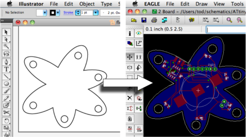
Eagle is a great cross-platform, free-for-non-commercial-use tool for many of us designing our own circuit boards. But it has a pretty glaring omission: the ability to import vector artwork to use as board outlines, logos, etc. You can import bitmaps via the finicky “import_bmp.ulp” ULP add-on, but bitmaps can’t work for board outlines. So we struggle with Eagle’s rudimentary vector drawing tools or have boring rectangular or circular boards. I think I’ve found a way to robustly transfer vector artwork from Illustrator to Eagle. Below I show an “amoeba” vector shape in Illustrator being converted and used as a board outline in Eagle.
The short version of the steps are:
1. In Illustrator, add many extra anchor points
2. In Illustrator, export artwork as R13 DXF format
3. In Eagle, run the “import_dxf_polygons_v4.ulp” on the exported DXF file
4. Use resulting shape in your circuit
This is a fundamentally cross-platform technique: no special binaries needed, like some Windows-only DXF converters. Also, it should work for any other vector program that can export to a DXF format. And since the Eagle importer is public domain and freely inspectable, it can be improved over time. The importer is currently limited in many ways, but seems pretty usable, given appropriate input.
Step 1: Add Extra Anchor Points to Shape
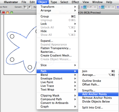
The import command in Eagle produces only straight lines as output – any curves in your shape will be approximated by straight lines. To get around this, add extra anchor points/nodes to your shape. Add enough until you feel comfortable that the number of extra points sufficiently describes your shape. In Illustrator, this means running the “Add Anchor Points” repeatedly. You can find the command under the Object/Path menu:
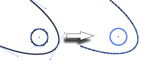
Zoom into your shape when adding anchor points to see the points being added. Here’s a before-and-after of part of the amoeba shape:
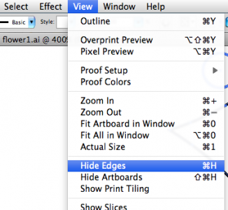
If you don’t see the anchor points on your shape, be sure “Hide Edges” is turned off under the “View” menu.
Step 2: Export Shape as DXF
Illustrator supports exporting to DXF files natively. For importing into Eagle, we want the older R13 version of DXF. Here’s the settings I use in the DXF export dialog:
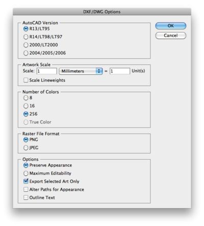
Be sure to place your shape as close to the lower left of the page in Illustrator, otherwise the shape will be far away from the origin in Eagle. (which is at the lower left)
Step 3: Import into Eagle
The DXF import is performed by the ULP “import_dxf_polygons_v4.ulp“. It is an updated version of the nice “import_dxf_polygons.ulp” extension written by Tim Ruetz and originally available from the Cadsoft Eagle userfiles misc area. I modified it slightly to let you select between WIRE (outline shape) and POLYGON (filled shape). Also, with WIRE, you can import unclosed objects, which you can’t do with POLYGON. Download the updated version here: “import_dxf_polygons_v4.ulp” and remember where you saved it.

In Eagle, from the Board window of your design, click the “ULP” button on the toolbar. Eagle will open up a “Run” file dialog. Navigate to where you downloaded the “import_dxf_polygons_v4.ulp” file and open it. You will be presented with a second file open dialog for “DXF file to import”. Navigate to your exported DXF file and open it. Then you’ll get the main import dialog:
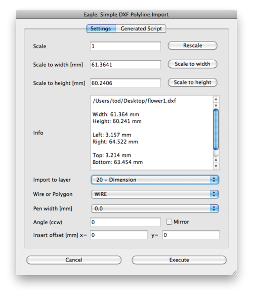
From here you can rescale and mirror the shape if need be. The most important option is arguably the “Import to layer” one. For board outlines, use the settings:
– Layer: “Dimension”
– Type: WIRE
– Pen width: 0.0
When you click the “Execute” button, the shape will be placed into your board.
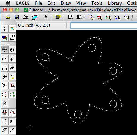
If you can’t see your shape, click the “Zoom Fit” button to fit all objects in the window. (the one to the right of the ULP button in the Zoom area of the toolbar) Now place your shape using a Group move.
Be careful using the POLYGON type. For shapes with interior holes, like the amoeba in this example, a POLYGON will fill in those holes, probably not what you want:
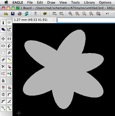
In most cases, use the WIRE type instead. It will also let you use open shapes like a spiral:
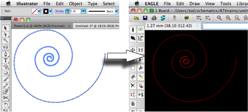
This isn’t useful for board outlines (which need to be closed), but could be useful for custom traces.
Let me know if you use this technique, or improve upon it. I think I’m going to try making this crazy little amoeba board that has an ATtiny on it, a bunch of LEDs, some I/O pins and a battery pack. :-)
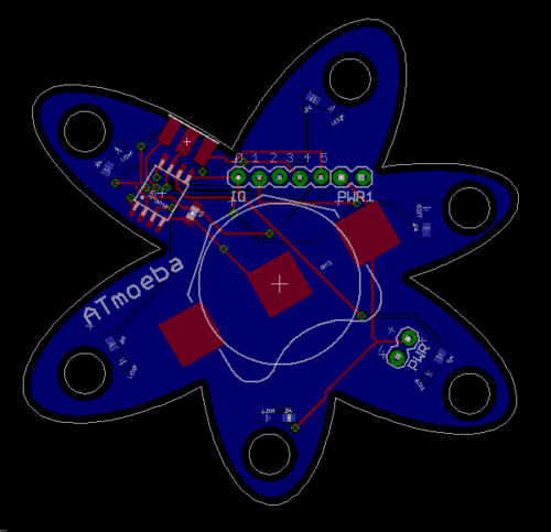
(thanks to Carlyn for the inspiration and help in figuring this out, particularly in how to wrangle Illustrator)

thanks a lot for this tutorial, it is just that i was looking for, i had a hard time to make this kind of design in eagle, and i could not find a way how to design stuff like you show,
thanks again!
best
danil
Thanks for this tutorial. I like how it’s not platform-specific. I was wondering if you knew of an open-source vector graphics editor you can use for editing the anchor points? I’ve tried Inkscape, but it doesn’t do nearly as good of a job at closing curves as Illustrator does.
Thank you so much, I had almost given up on putting fancy designs on my PCB, with deadlines looming this was my last hope. Needless to say it worked!
Thanks so much for putting this up. Worked great for me!
You are my hero! I was looking for this for the past several years, thank you. BTW, the DXF R12 export form Inkscape works too. Thanks so much for being sane (cross platformness).
Thanks for the tutorial!
I can’t see my imported file dough… Already did zoom to fit and dimension layer where I put the file is on…
Any suggestions?
Awesomely helpful, Tod.
I really struggled with svg->bmp, then import, but never got the results I was hoping for in milling my boards. Looking forward to trying your technique.
Thanks!
DW
You can straighten them out after adding more points with Object > Path > Simplify in Illustrator and selecting the “Straighten Lines” option.
Oh, also if you don’t see a layer you want to import to after loading the ULP – make sure it is visible.
I made a learning-experience version of the NASA logo using this code.
http://goo.gl/iJLb0
Hi Bill,
Thanks! I couldn’t find a way to convert curves to straight lines in Illustrator nor in Inkscape, either as an operation on the shape or as an export option. If you find something, let me know.
And yeah I figured those interior cusps wouldn’t be fabbable. But thankfully, it’s now a pretty easy task to redraw the shape and re-import it. :)
Nice tutorial, I particularly like the generality. As you say, the concepts should work with other SW as well.
Isn’t there an option when exporting to export as straight line segments rather than “curves” (thereby avoiding the need to add the extra anchor points?
On you amoeba, note that those sharp angles on the insides of the lobes won’t be achievable with most routers…
Wow, this is an awesome tutorial, Tod! Thanks!