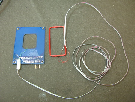
The Parallax RFID reader is a pretty cool bit of tech. For $40 you get a reader with integrated antenna that outputs ASCII at 2400bps. Unfortunately, the integrated antenna means you can’t place RFID tag sensing in tight spaces. You can however circumvent the built-in antenna and add your own. With a remote antenna of your own creation, you can customize its size and shape to fit your application.
First, locate the two places where the circuitry connects to the
antenna. (click the images for larger versions with notes)


Then using an Exacto knife or similar device, scrape away the traces leading to the antenna. This disconnects the built-in antenna. Then scrape away some of the solder mask on each of the traces leading to the circuit and solder down some fine wire. I use wire-wrap wire.


The two wires soldered can then be led to a jack of some sort. I used a 2-pin Molex header I had laying around. Now you can fashion a remote antenna.
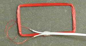
To fashion an antenna, you need to create a >1/2″ diameter loop of about 100 turns of 30-gauge enameled solid-core wire (aka “magnet wire”). Radio Shack sells a pack of magnet wire that fits the bill just fine. Wind the wire around something handy, then keep it together with clear fingernail polish. Use a lighter to remove the enamel and solder wires to it.

If you have an inductance meter, use it to make sure the inductance is between 500-1000 uH.
If the inductance isn’t high enough (i.e. not enough turns) the RFID reader just won’t work and you may even damage it. But then, if you’re taking an Exacto to your reader, you’re probably not so concerned about that.


Hi everyone! for the parallax reader, can i create multiple antenna after i disconnect the built in antenna?
Sorry a 3′ by 2′ area.
Thanks
Looking for a reader that I can extend the antenna to read a 3″ by 2″ area. Any suggestions?
Hi Gush,
My understanding is that at 13.56MHz it’s best to make using a PCB, where the traces on the PCB form one or more inductors and a couple of capacitors are placed next to the traces to form the resonant LC circuit needed. It’s a lot more complex than the rather simple single loop + single capacitor of the 125kHz antenna, but there are many application notes on how to design the PCBs.
Also, an L/C meter just measures either an isolated inductance (L) or capacitance (C), and doesn’t really have a frequency component. It cannot produce meaningful measurements on a resonant circuit like the complex antennas used on 13.56MHz RFID readers. The L/C meter I use is this one:
http://www.aade.com/lcmeter.htm
Hi Tod,
Would home-brewing a remote 13.56MHz antenna for something like the Skyetek readers require a LC meter that could sample at 13.56MHz? Also, were you just matching the inductance of the antenna on the PCB, or did you calculate what you were going for? Any detuning because of the leads to the remote loop?
Thanks!
ioan, that’s pretty hard. The antenna is embedded in the PCB the reader circuit is on. It would be pretty easy to slip with the cutting tool and destroy the circuit.
What about cutting off the old antenna and use the old antenna (that you just cut off) as a remote antenna?
So did the hack of ASPX RW210, 13.56 ever happen? If so any details would be appreciated. Thanks!
Hi Alain,
Unfortunately, no. The Parallax RFID reader (like most low-frequency readers) are designed for a specific frequency and protocol. In the Parallax reader’s case, it’s designed for the EM410x protocol which is at 125kHz.
Hellow i need to use this rfid the parallax to read the glass rfid for animal uses and the frecc
is like 134,2khz how i make or is posible to modifi the software or the hardware for read this freccuencie thans
A Durot
Hi Koyote,
Not a dumb question at all. Unfortunately, the hack as presented effectively replaces the original antenna. You can use the original antenna by sticking a jumper across the two-pin jack that was added. So in theory you could put a relay in that that lets you programmatically switch between one antenna or the other. But having both at the same time I think would be a no-no.
I’m sorry for the stupid question but with this hack(connected the built-in antenna too) both antennas will work? i would like to do this to use my reader on very thick door having the RFID reader on the inside and the external antenna outside.
Thanks
Hello,
I’d like to know what’s the formula which relates reading distance, diameter of the coil, and number of turns for 125 kHz RFID systems? Let’s say I wanna be able to read a tag placed at 20 cm: what should be the diameter and the number of turns of the antenna?
Best regards!
Increase the reading distance of RFID antenna depend on size of your antenna, reader power. Of course there are physics limitation of how big the antenna will be. Able to properly tune the antenna is another problem you are facing. What is the read distance work for you ?
Hi Michael,
At HF frequencies like your TI RFID, you have to start paying attention to properly tuning the antenna lines so the impedance matches. That’s not a simple task. Tuning isn’t that critical in the LF frequencies used by the 125kHz RFID of the Parallax reader.
Hey,
I am working on increasing the range of a 13.56 MHz TI reader and will this set up work for my system? If so, what are all of the parts required? Great how-to on making this, but if you could post all the required components, would greatly appreciate it. Thanks.
I hacked the phidgets rfid reader back in June, then the Parallax in July.
http://forums.trossenrobotics.com/showthread.php?t=1006&highlight=rfid
The parallax works best with a 699uh external coil, we have a custom manufactured coil that’s only 40mm diameter, that’s about as small as they get. The other problem with the parallax, is that it’s not a particularly high powered rfid reader, so the effective read range is somewhere between 2 and 5cm, depending on the tag size and angle of reflection. We’ve hacked cheaper 125khz USB readers from China, and got ranges up to 10cm through dense plastic, and without the need to angle the TAG.
Needless to say, any reader with an inline coil can be hot-wired, but finding the right coil may take a bit of trial and error.
Next one up for the chop – the ASPX RW210, 13.56, inline – they say it can’t be done, I say it can :)
– JR
Hi Marco,
Yes, with a shear or a steady hand with a Dremel, you could cut off the unused built-in antenna. As for a compact antenna, I’m not sure. I don’t know much about the physics of it, but I suspect since all the 125 kHz reader antennas I’ve seen are implemented as coils, it’s not possible.
Very good modding, but I have two questions:
1- Is possible to break the circuit board so reducing the size of the reader (obviously with the new antenna plugged)?
2- Is possible to realize a supercompact antenna using Ferrite to increase the magnetic field (like in the glass RFID tags)?
Regards
Marco