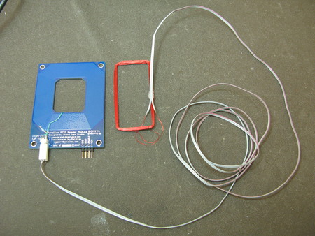
The Parallax RFID reader is a pretty cool bit of tech. For $40 you get a reader with integrated antenna that outputs ASCII at 2400bps. Unfortunately, the integrated antenna means you can’t place RFID tag sensing in tight spaces. You can however circumvent the built-in antenna and add your own. With a remote antenna of your own creation, you can customize its size and shape to fit your application.
First, locate the two places where the circuitry connects to the
antenna. (click the images for larger versions with notes)


Then using an Exacto knife or similar device, scrape away the traces leading to the antenna. This disconnects the built-in antenna. Then scrape away some of the solder mask on each of the traces leading to the circuit and solder down some fine wire. I use wire-wrap wire.


The two wires soldered can then be led to a jack of some sort. I used a 2-pin Molex header I had laying around. Now you can fashion a remote antenna.
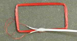
To fashion an antenna, you need to create a >1/2″ diameter loop of about 100 turns of 30-gauge enameled solid-core wire (aka “magnet wire”). Radio Shack sells a pack of magnet wire that fits the bill just fine. Wind the wire around something handy, then keep it together with clear fingernail polish. Use a lighter to remove the enamel and solder wires to it.

If you have an inductance meter, use it to make sure the inductance is between 500-1000 uH.
If the inductance isn’t high enough (i.e. not enough turns) the RFID reader just won’t work and you may even damage it. But then, if you’re taking an Exacto to your reader, you’re probably not so concerned about that.


@Matthew Hall – how many turns did your final antenna have? I don’t have an original antenna to work with, so I’m flying in the dark, trying to match up the 1.08mH my RFID reader needs (ID-2). It’s a shot in the dark, I know, but a manufactured an antenna or a reader with a built in antenna will be cheaper than an oscilloscope if I can’t get mine to work… :)
This is great, Matthew! I’ve always wanted a way to do this that didn’t use a inductance meter. (I told those who asked to just do 100 winds of 30 gauge magnet wire, a sloppy solution that usually works to some degree)
So, in case anyone is wondering how best to build a coil to match the one on the reader, when one has no access to an inductance meter (though having access to either a scope or a frequency meter), here’s how I did it:
I did the same thing as in these instructions, but I also soldered two extra wires onto the PCB antenna (i.e. on the other side of the cut trace). I then built a simple Colpitts oscillator, which is an oscillator whose frequency depends on the inductance of a coil. Its a single NPN transistor, a couple of caps, and a couple of resistors. The schematic I used can be found here:
http://www.falstad.com/circuit/e-colpitts.html
There are more robust Colpitts circuits out there, but that one worked well (plus the little Java animation is edumacational!). Once you have the circuit built, plug in the coil from the PCB card, and measure the frequency with either a scope or frequency counter (I got about 50 kHz on mine).
Then, to build your coil, use a formula, or a calculator like the one at the bottom of this page:
http://www.zen22142.zen.co.uk/Theory/tunedcct.htm
I built mine on an 8″x8″ frame, since I wanted it to be something my cat could walk through. I used the inductance formula to come up with an initial estimate of 40 turns, and then (burning off a bit of enamel on the magnet wire), tested it in the same Colpitts circuit, and found that I was a fair bit slow (only about 25kHz!). So I took off about 8 coils, and tried again. I continued in this fashion until I got something within spitting distance of same frequency that the PCB gave me, and then attached it to the RFID circuit. It worked very well right off the bat, reading the card starting at about 6 inches away at a variety of card/coil alignments.
Anyway, beyond the scary bit where I had to scrape off the insulation from the tiny traces without destroying the board, it wasn’t that hard to add an external antenna. Thanks, Todbot!
How long can the connecting wire to the antenna be – I am looking for maybe 18 feet?