The notes for the fourth and final class are up on the Spooky Arduino class page. At the end of the class, Mark of Machine Project bestowed upon each of the students a merit badge. It was great. Click above for a larger view of the badge.
Arduino MIDI Drum Kit and Spooky Sound Trigger
Here’s a quick project using techniques from this week’s class that turns an Arduino board and a few buttons and piezos into a MIDI drum kit or scary sound trigger. Hide piezo sensors around the house during your Halloween party to trigger scary sounds when people walk around!
Hardware
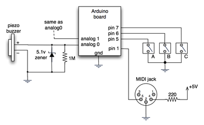
The hardware is an Arduino board with a MIDI jack, a few buttons, and two piezos attached to it. It runs off of a 9V battery.

(Note: depending on what kind of MIDI connector you’re usign (jack or cut-off cable), you may need to swap the connections to MIDI pins 4 & 5).
For the piezo input, the 1M resistor is to bleed off the voltage generated by the piezo when it is struck. The 5.1v zener diode is there to insure any large voltages don’t make it into the Arduino and blow it out.
Arduino code
The code has a few tricks that may not be immediately obvious. First is that to implement a MIDI interface, all you really need is the ability to send serial data at 31,250 bps. This is easily done with “Serial.begin(31250)“. Once that is done, a complete three-byte MIDI note-on message can be sent with three “Serial.print(val,BYTE)” commands.
The next tricky bit is that the switches in the above schematic don’t need pull-up resistors. This is because the internal pull-ups in Arduino’s AVR chip are turned on with a “digitalWrite(pin,HIGH)“. This may seem counter-intuitive, doing a digitalWrite() on an input pin, but it’s how the AVR works. The benefit is that you no longer need a resistor to +5V and the effort to wire up each additional button is much lower.
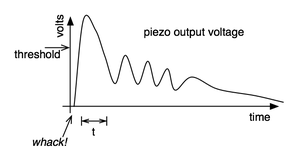
The final trick is measuring impact force on a piezo. When piezo elements are struck, their output voltage rings, sort of like a bell. Kind of like this:

By measuring the time it takes for that first big jolt to cross a threshold, you can get an idea as how big the force was. In the code this is represented by reading the analog value and if it’s over the threshold, wait until it drops down again, counting all the while. When I’ve done this before, I used an input opamp to convert the analog signal to digital (thus doing thresholding in the analog domain) and then used interrupts to get very accurate force measurements.
Arduino code: midi_drum_kit


Hi David,
That LabJack you mention is mostly for data collection in labs, I’m not sure how well it would work in a real-time environment. That is, it contains no intelligence, just inputs & outputs. The Arduino contains a small computer that can act on its inputs and twiddle its outputs
As for which piezos, generally the rule is “get the cheapest”. You want to get “piezo elements” and not “piezo buzzers”. The latter contain driver circuitry to make noise. I believe the piezo elements from Radio Shack I’ve had success with is 273-073.
great tutorial. I am trying to do the same thing for learning purpose. I’m a programmer but I don’t know anything about electronic.
I stopped by radioshack last night and they have so many different piezos that I didn’t know which ones to buy. Is there a ref number on the one you stripped down?
I was also looking into the labjack U3 from http://www.labjack.com/labjack_u3.php?prodId=25
Do you think this would work?
Thanks for your time
-David
Hey again. :) I’m starting to make some great progress on trying this out. I built a full kick pedal with the sensor integrated…
check it out: http://somesoundswelike.com
I’m running into the double or triple triggering problem… I have a few ideas about how to defeat it, but if you have any insights, I’m all ears.
thanks as always! your content is freakin’ awesome, and stays awesome for a long time. :)
-steve
I’m working on a similar setup but using a pic 16f690 instead. I found a PC serial midi driver that works great so far:
http://www.roland.com/products/en/_support/dld.cfm?iCncd=724&ln=en&SearchBy=RcId&dst=P&iRcId=0000010777&dsp=1
The only trick is that you should set the serial port speed to 38400 instead of the midi spec speed of 31250. Apparently due to integer boundary timing :) Either way, I hooked up using the standard serial port and the few midi monitor program I tried saw the driver and got the midi messages exactly as sent.
Thanks for the nice video and project todbot!
Thanks to mschaff for good details on constructing cheap pads.
My question is how many levels of velocity can this code/hardware accurately measure? Talking with an audio buddy, he didn’t think software would have more than 3-7 velocity levels for any given drum channel. If this simple hardware can achieve that then I’d be more than satisfied since I prefer simple hardware (being a software person) and am not a drummer.
hey man, great tutorial, I was wonderng if you had any insite into how to do the oposite, taking midi data (a midi file) and getting it to control some external device (using the Arduino)
http://code.google.com/p/s2midi/ or here http://www.memeteam.net/ has a serial to midi translator app for windows just fyi, no reply required
Hi Daniels,
I’ve not seen your code, so I can’t tell you for sure, but I bet it’s a misplaced curly-brace for the initial “if()” statement.
Excellent stuff ! managed to adapt it to take 5 peizos and finally got it working ( as i have no previous programming experience). However i noticed when monitoring the incomind midi signal that there are often more note off messages than note on,and i cant figure this out, this was also the case before i expanded the code to include 5 piezos. Do you know why this happens and if it can be sorted ?
very good stuff todbot.
comments of other users (willem & mschaff) are very interesting, it gave me new idea to clone the monome with velocity pads (!).
yes, u have to improve your midi langage, this will give you more possibilities.
Hi Patrick,
You are entirely correct. As I mention in the comments above, the “noteOff as noteOn with zero velocity” is not a bug but a purposeful lazy hack that I’ve been doing for a long time and should probably stop now that I’ve received multiple comments on it. :)
I may be wrong but there is something in your .pde code which is funny:
You use
midiMsg( (0x80 | (channel<<4)), note, velocity);
for noteOn and noteOff messages.
In fact, it should be 0x80 for noteOff, and 0x90 for noteOn.
And, instead of (channel<<4), you should use (channel-1).
Interestingly, your code works because as you are only using channel 1, 0x80 | (channel<<4)) gives 0x90 (which is the code for noteOn).
And so for noteOff, you send a noteOn with a velocity of 0 (which is interpreted as a noteOff by all synths, but is not exactly the same thing… as it is possible in MIDI to have a noteOff velocity).
Hi there,
Thanks for your info!
I’m building a led-system into my drumkit and your trigger-diagram helped me to generate a nice input for my microprocessor. About your analog inputs, you can link buttons parallel with several different resistors and use just one analog input to read which button is pressed. By using for instance 1k, 2k, 4k, and 8k, you can read exactly what buttons are pressed using just one input.
byebye
Thanks a lot for the tutorials. This opensource is indeed exiting and revolutionary.
Anyways, I’m new to microcontrollers and arduino, (have a little coding experience though)
You mention input buffers for better control of the piezos. I found some information about loading down the piezos with several 10Meg resisters and then buffering the output voltage with an op amp such as the U1-A.
I was wondering if this would work, and, if it would help anyone, to link to the information…
http://www.musicfromouterspace.com/analogsynth/SOUNDLABMINISYNTH/drum_trigger.html
Hi, great post. I wrote a Mac OS X application that creates a virtual MIDI instrument from Arduino serial output. This eliminates the need for the MIDI module as you described. I made an electronic drum kit out of it. See: http://code.google.com/p/ardrumo/ for details.
Oh, and btw: the NYU Computer Store sells the “midi jacks” as “5 pin DIN connectors” for $1.45.
Ben: just remember to swap pins 4 and 5…
Tod, thanks so so much for the tutorial (and all the stuff on your site).
You won’t believe how frustrated I’ve been tonight. I went over my connections a trillion times, but could not understand why I wasn’t getting any midi out from my Arduino……until I read Rob’s post about swapping pins 4 and 5 – which I did, and now everything is working perfect.
Thanks again, and thanks Rob! :)
I’ll send you info on my project when I’m done.
Hi Ben,
If you’re looking for a “midi jack” on Jameco or Digikey, you probably won’t find it. The real name is something obscure like “5-pin 180º DIN jack receptacle with female sockets”. The cheapest/easiest might be just to get a “PC/AT keyboard extender cable” or even just a MIDI cable and cut them in two. I’ve done that several times.
If you want a proper jack you can solder to, here’s one from Jameco.
Any idea where to get the MIDI Jack from online? I tried a few google searches, but no luck, nor from the component sites listed here. Thanks in advance!