![]()
The notes for the fourth and final class are up on the Spooky Arduino class page. At the end of the class, Mark of Machine Project bestowed upon each of the students a merit badge. It was great. Click above for a larger view of the badge.
Arduino MIDI Drum Kit and Spooky Sound Trigger
Here’s a quick project using techniques from this week’s class that turns an Arduino board and a few buttons and piezos into a MIDI drum kit or scary sound trigger. Hide piezo sensors around the house during your Halloween party to trigger scary sounds when people walk around!
Hardware
The hardware is an Arduino board with a MIDI jack, a few buttons, and two piezos attached to it. It runs off of a 9V battery.
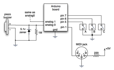
(Note: depending on what kind of MIDI connector you’re usign (jack or cut-off cable), you may need to swap the connections to MIDI pins 4 & 5).
For the piezo input, the 1M resistor is to bleed off the voltage generated by the piezo when it is struck. The 5.1v zener diode is there to insure any large voltages don’t make it into the Arduino and blow it out.
Arduino code
The code has a few tricks that may not be immediately obvious. First is that to implement a MIDI interface, all you really need is the ability to send serial data at 31,250 bps. This is easily done with “Serial.begin(31250)“. Once that is done, a complete three-byte MIDI note-on message can be sent with three “Serial.print(val,BYTE)” commands.
The next tricky bit is that the switches in the above schematic don’t need pull-up resistors. This is because the internal pull-ups in Arduino’s AVR chip are turned on with a “digitalWrite(pin,HIGH)“. This may seem counter-intuitive, doing a digitalWrite() on an input pin, but it’s how the AVR works. The benefit is that you no longer need a resistor to +5V and the effort to wire up each additional button is much lower.
The final trick is measuring impact force on a piezo. When piezo elements are struck, their output voltage rings, sort of like a bell. Kind of like this:
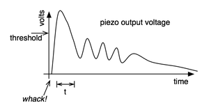
By measuring the time it takes for that first big jolt to cross a threshold, you can get an idea as how big the force was. In the code this is represented by reading the analog value and if it’s over the threshold, wait until it drops down again, counting all the while. When I’ve done this before, I used an input opamp to convert the analog signal to digital (thus doing thresholding in the analog domain) and then used interrupts to get very accurate force measurements.
Arduino code: midi_drum_kit
Hi Wyatt,
Very nice. And awesome project writeup. I’ve had many people ask if the Arduino could be made into a good electronic drum brain and while I’ve said it could be done, I’ve not (until now) had a good example to point them at showing that it could be done well.
Hey there,
I had found your site back in February, and had decided at that time to make a real, professional grade EDrum set using the Arduino. The initial prototypes were closely based on our work, but it evolved past that. If you (or anyone else reading this) are interested, you can check out the website http://drummaster.thecave.homeunix.org.
While my design is not MIDI based, it is generic enough that you should be able to substitute the MIDI code and instructions found here, and replace my custom serial protocol to make a true MIDI drum set. (The reason I chose not to use MIDI is that my own protocol, along with the slave software running on the computer, is much more customizable and (IMHO) powerful than a MIDI based solution would be.)
Drum Master, with the associated Drum Slave software, allows up to 32 analog (velocity sensitive) inputs and 8 digital switches, has ports for 16 drum pads, allows up to 6 zones for each pad (by using RJ45 ports, you can get GND, V+ (for active electronics such as accelerometers / LED sensors), plus 6 data channels), etc. Full schematics, PCB layouts, software, images, movies, etc are on the site. Everything is licensed under a CC license.
I have a couple of shields left over from the PCB run, if anyone is interested in the ‘official’ version; you can contact me for details.
Cheers
Hi Mattias,
You don’t need a shield, but you’ll find that having a solderless breadboard to be a very useful add-on to an Arduino board, for this project and in general. If you’re looking for a really simple and inexpensive solution, take a look at this 1¢ under-shield idea. :)
Hi!
This is really what I’ve been looking for. An easy MIDI-drum. My question is: do I need that green “Proto-Shield” or can I make it with just a “Arduino Diecimila USB board”? I have never seen the Arduino board before..
thanks!
– Mattias
Hi Tod,
thanks for the advice about using a MUX to “increase” the analogue inputs on the Arduino. I’d like to interface with MaxMsp but am struggling with the code. The piezo seems to trigger all the inputs on Arduino out of the MUX. Is there anyone who could offer advise on the code. Also, is there any schematics for interfacing an ADC to also increase piezo inputs by utilising the digital i/p on the Arduino.
Thanks
Hi Mark,
Do you have the buttons hooked up exactly like the schematic I have above? I did a bit of trickiness with the buttons that is easy to miss. When hooking up buttons, you normally need a “pull-up” or “pull-down” resistor. See the Arduino Button tutorial for an example with a pull-up resistor. If you have some 1k to 10k resistors, try hooking them up as in that tutorial and see if that solves your problem.
The trickiness I did was to use the internal pull-up resistors that are part of the chip in Arduino. That’s what the:
digitalWrite(switchAPin, HIGH); // turn on internal pullupline does and you need one per switch.
The other thing to realize is that when the switches are hooked up like this, they produce a LOW when pressed.
I’m currently building a midi controller to interact with ableton live and your project has helped a lot. I’ve got several pots all hooked up and working but I’m having problems with the coding for the buttons to trigger the clips in live. Have you done anything similar? Do you have any examples that might help?
Thank you in advanced.
Mark
Hi Mike, yes, there are many MIDI adapters for your computer. Usually around $40 or so. For instance, there’s the M-Audio Uno that I’ve heard works well.
Is there a midi module that i can use that is at a reasonable price range? roughly no more than $200 or less?
so here’s my current arduino sketch to test trigger values/enveloping on all six analogue inputs in a state machine with no inner loops (other than the one to traverse all six inputs)…
int led = 13; int env[] = {128,384,256}; byte s[6]; int i[6]; int v[6]; int t[6]; int x = 0; void blink(boolean b) { digitalWrite(led,b ? HIGH : LOW); } void setup() { pinMode(led,OUTPUT); for(x = 0; x < 6; x++) { s[x] = 0; i[x] = 0; v[x] = 0; t[x] = 0; } Serial.begin(57600); Serial.println("----"); } void loop() { for(x = 0; x env[0]) { s[x] = 1; t[x] = 0; blink(true); } } if(s[x] == 1) { i[x] = analogRead(x); if(i[x] > env[1]) { s[x] = 2; } t[x]++; } if(s[x] == 2) { blink(true); Serial.print(x); Serial.print(";"); Serial.print(i[x]); Serial.print(";"); Serial.println(t[x]); i[x] = analogRead(x); v[x] = max(v[x],i[x]); t[x]++; } if(i[x] < env[2]) { s[x] = 0; blink(false); } delayMicroseconds(1); } }i intend to set up a few experiments this weekend, graph and compare what i get out of a zener versus a 200v peak inverse rectifier (in4003), both going to a 1mohm resistor and finally a capacitor… (i’ve got a theory about using a rectifier instead of a zener.)
have no idea what capacitor will work best… though i think i like the sound of ‘2.2µF 50V 20% Nonpolarized Electrolytic Capacitor 9,000Hz’.
as for the envelope detection/correction i’ll stick with doing it in my sketch and modify the heck out of a state machine to manage all 6 inputs.
i’ll post my findings when i’ve got ’em! :)
Hi Kris & Fabi, Yup, that algorithm you mention Kris is basically the one implemented in the original Arduino sketch above. The general term is “thresholding” or “comparator”. I found in my experiments that measuring the signal via thresholding was more reliable that measuring peak voltage for piezo signals.
That PAIA page linked by fabi is great and very instructive. It contains two very useful sub-circuits: a peak detector and a voltage buffer. In the Arduino circuit above, I was hoping the intrinsic capacitance and built-in diodes of the AVR’s input pins would be enough to act as peak detector. And that the high-impedence of the pins would not require the use of an op-amp buffer.
I think I used that very PAIA info when I built my senior EE project: “perc-a-lator”, a trigger-to-MIDI converter, back in 1992. (schematic here) I omitted the op-amp buffer that’s in the PAIA circuit because the microcontroller I used also had high input impedance and a fast A/D.
mm, just realized a required slight modification to the above algo — while in the while loop waiting for a ‘decay’ voltage, add an if statement to update the ‘attack’ voltage if you get a reading higher than the initial ‘attack’; this will account for cases where the ringing of the piezo is slightly delayed.
i had also recurring thoughts of ‘capacitor’… what if: you added a capacitor after the diode and resistor (both to bleed off more severe strikes), then, follow this algorithm, in your loop() — 1. take a reading of the voltage coming off the capacitor — 2. if it meets your ‘attack’ voltage, set a counter to zero — 3. while the voltage is greater than a ‘decay’ voltage, increment your counter and delay (by 1ms?) — 3a. if your counter is greater than some max value, break out of the while loop — 4. once out of the while loop, evaluate your counter versus the initial ‘attack’ voltage reading… the two together should give you some indication of how hard the piezo was struck as well as how long it took the capacitor to discharge i.e. how much energy was stored into it as a result of the strike velocity, and thus, you’ve got one velocity reading… obviously this adds some latency into evaluating each strike but depending on the type of capacitor used the discharge could happen very rapidly.
I’ve made a drum-trigger with arduino, based on your project among others, and i solved some issues (as double/triple trigger on a note) just by using a peak-detector. Results are smoother than using a single piezo. A simple peak-detector is made with a diode, a capacitor and a dicharge resistor. I found some interesting info about this topic at Paia’s web:
http://www.paia.com/ProdArticles/drumsens.htm
This works by charging and discharging a capacitor (and using an op-amp after), so i think it’s not by “on” duration, but by the charge level of the capacitor when being discharged, so you can measure variable voltage on output. You can use a pot too, and then you can increase and decrease the threshold (sensivity) for a drumpad.
Keep rocking!
You got it, Kris. The real trigger-to-MIDI converters have a per-input op-amp input state to condition the piezo input, very much like an envelope generator. Though I think their op-amp circuits are more like comparators that convert the piezo input to a on/off signal, where the ‘on’ duration indicates the velocity of the input strike.