
![]()
The notes for the fourth and final class are up on the Spooky Arduino class page. At the end of the class, Mark of Machine Project bestowed upon each of the students a merit badge. It was great. Click above for a larger view of the badge.
Arduino MIDI Drum Kit and Spooky Sound Trigger
Here’s a quick project using techniques from this week’s class that turns an Arduino board and a few buttons and piezos into a MIDI drum kit or scary sound trigger. Hide piezo sensors around the house during your Halloween party to trigger scary sounds when people walk around!
Hardware
The hardware is an Arduino board with a MIDI jack, a few buttons, and two piezos attached to it. It runs off of a 9V battery.
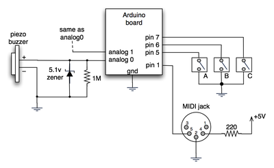
(Note: depending on what kind of MIDI connector you’re usign (jack or cut-off cable), you may need to swap the connections to MIDI pins 4 & 5).
For the piezo input, the 1M resistor is to bleed off the voltage generated by the piezo when it is struck. The 5.1v zener diode is there to insure any large voltages don’t make it into the Arduino and blow it out.
Arduino code
The code has a few tricks that may not be immediately obvious. First is that to implement a MIDI interface, all you really need is the ability to send serial data at 31,250 bps. This is easily done with “Serial.begin(31250)“. Once that is done, a complete three-byte MIDI note-on message can be sent with three “Serial.print(val,BYTE)” commands.
The next tricky bit is that the switches in the above schematic don’t need pull-up resistors. This is because the internal pull-ups in Arduino’s AVR chip are turned on with a “digitalWrite(pin,HIGH)“. This may seem counter-intuitive, doing a digitalWrite() on an input pin, but it’s how the AVR works. The benefit is that you no longer need a resistor to +5V and the effort to wire up each additional button is much lower.
The final trick is measuring impact force on a piezo. When piezo elements are struck, their output voltage rings, sort of like a bell. Kind of like this:
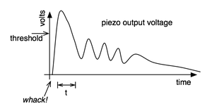
By measuring the time it takes for that first big jolt to cross a threshold, you can get an idea as how big the force was. In the code this is represented by reading the analog value and if it’s over the threshold, wait until it drops down again, counting all the while. When I’ve done this before, I used an input opamp to convert the analog signal to digital (thus doing thresholding in the analog domain) and then used interrupts to get very accurate force measurements.
Arduino code: midi_drum_kit
and taking the analysis of the problem a step further… one could also investigate the properties of envelope generators of analogue drum machines which are particularly good at very sharp decay… you could apply an EG to each piezo and then you really would just be seeing one significant peak to be compared to your threshold.
so i managed to get an RBBB assembled (really bare bones board – check out http://moderndevice.com ) and working last night to the extent of sending midi out to a korg esx-1, just playing scales over several octaves… so challenge met halfway…
i’ve been reading the posts here and regarding the multiple ‘strikes’ issue – i have to wonder if the key isn’t simply adding, as tod suggested in the original diagram – the diode and resistor to the signal path of each piezo… i’d be very interested in graphs showing the ringing effect with and without several grades of diode and resistor values.
also, what’s the response time of a power regulator ic? perhaps that may be used, or used in conjunction with a diode and/or resistor, to normalize the impacts even more… so that you don’t have issues associated with some strikes going so beyond your target threshold that even some of the rings qualify as additional hits as well.
Hi! You don’t need the minikorg. But you will need a hardware MIDI interface for your computer (~$40). Or you could run a converter program to convert the Arduino’s USB serial messages to internal MIDI messages. A few of these converter programs are mentioned above. Also, poke around the Arduino forums and you’ll find others.
Hello guys..
well.. Super! i’m looking for arduino exactly as a midi interface..but i want to use this with Live ableton…
Can u connect that ddirectly to live ableton?? without the minikorg?
I’ve been banging my head against the wall on the piezo double/triple trigger problem… still. :) I used tom igoe’s sensor reading and charting technique and have something resembling actual science now.
please come take a look and leave a comment…
http://www.somesoundswelike.com/2008/02/02/diy-drum-triggers-reading-the-sensor-scientifically/
I’m thinking about the multi-sensor problem, too. Although, i think you could limit it to 4 concurrent sensor readings, since you typically only have 4 appendages that you can hit sensors with at any given moment… I dunno if that really helps the problem or not, but it’s something I’ve been thinking of.
In the previous post I should really have said explicitly that the idea is that you can have a call to checkButtons() or whatever in each pass through loop().
Or better still, leave out the while altogether and check for needing to do an action each time through loop(). E.g. something like:
boolean thingHappening = false;
int startTime;
loop() {
if (someCondition) {
doFirstThing();
startTime = millis();
thingHappening = true;
}
if (thingHappening && ((millis() – startTime) >= 1000)) {
doSecondThing();
thingHappening = false;
}
}
The advantage of a “state machine” scheme like this is that you can have more than one thing happening at the same time.
I’m not sure about this but I think the Arduino code can lose characters received on the serial port during calls to delay() which are too long. delay() is convenient for quick experiments but I think it’s usually better avoided the moment you want to do anything a little bit complex.
Yeah it’s tough with microcontrollers because you can’t spawn a new thread or process to take care of stuff.
There are two ways to go about it. One way is to use interrupts. This is where you associate some external event with a chunk of code. Arduino supports a type of interrupt, so that might work for you.
The other way is to remove all delay()s from your code and instead use millis() or many shorter delays() to check if enough time has passed. For instance, instead of doing this:
you can instead do something like this:
  doFirstThing();
  for( int t=0; t<1000; t++ ) {
    delay(1);       // wait just a little bit
    checkButtons(); // button resp. fast now!
  }
  doSecondThing();
or something like this:
doFirstThing(); int starttime = millis(); while( (millis() - starttime) < 1000 ) { checkButtons(); } doSecondThing();Thanks for the answer!
This is exactly the problem I’m having with a different project. While being completely new to this microcontroller thing, I’m trying to figure out how to make the Arduino recognize/respond to button input during the (heavily delayed) loop. The buttons are speed up/down and mode left/right, changing the speed and sequence of a wad of LEDs (my newbie learning project).
Fun stuff, I’m used to writing PHP, and have never had to deal with concurrent events in my code. Kind of a waker-upper to not have a threading daemon backing things up :)
Hi Del,
You’re very perceptive. If you hit a button or piezo during the delay(), it won’t be read. I probably shouldn’t have done the delay like that. If you want, you should be able to make the delay small and constant (e.g. “delay(10)”). If you’ve set your MIDI device to “drum” or “trigger” mode then it shouldn’t matter how long the note is held for. But you should still send a note off to avoid the stuck-note issue of some MIDI modules.
Greetings todbot!
I recently got an Arduino and have used your projects quite a bit already. So first off, thanks! Very useful stuff.
I’m having an issue with one of my fiddling projects though and I think this particular project may help me fix my issue. So, here’s my questions for you:
In the following code;
noteOn(1,note_crash, t*2);
delay(t);
noteOff(1,note_crash,0);
What happens if you punch one of the buttons, or hit the high-hat, _during the delay_ between noteOn and noteOff? Does that instrument play as well? Overlapped with the current instrument, right after the current one finishes, not at all?
I watched the video a couple times, but just can’t quite figure it out that way. I also don’t have any midi anything around here to just try building the thing myself.
Thanks in advance,
Del
Hi keet,
That’s a really interesting idea, having the piezos in a matrix. My first instinct is that it’s not possible, because the piezo signal is analog (not digital) or because the loading of the other elements would make it hard to read just one.
But some more thought and some experiments would be warranted to say for sure.
Great project todbot,
In relation to those who were inquiring about more inputs, I am wondering if this might be possible using triggers set up in a matrix fashion similar to the way keyboards work. I know this wont be possible with the piezos but do you know if might work with switches on the digital inputs ?
[k]
Hi, I’ve tried the simple way, and I get almost the same lag:
val = analogRead(piezo);
if (val > threshold)
{ noteOn(0x90,note,val/8);
delay(1);
noteOn(0x80,note,0x00); }
With this code I also get double notes on one stroke, so I tried this other way:
val = analogRead(piezo);
if (val > threshold)
{ if (already_playing==0)
{ noteOn(0x90,note,val/8);
already_playing=1; }
} else
{ if (already_playing==1)
{ noteOn(0x80,note,0x00);
already_playing=0;}
}
delay(1);
This eliminates most of the double notes, but the annoying lag is still there… :(
I’m mostly on the side that it has to do with my board and the analog inputs, because the digital inputs have no lag at all.
Anyone here with the same board (Arduino NG) have succeeded with no lag?
Thanks,
Bran
Hi Bran,
The lag is likely not due to the A/D or the version of Arduino you have (I originally did this on an NG I think)
More likely (if you’re using my code above), it’s the part of the code that attempts to determine “velocity” of the hit on the piezo. Instead what you might want to try is just measure any hit at all. (like in the KnockSensor Tutorial)
If you don’t get any lag with that, it’s definitely an issue with the velocity-determining code (which is a real hack on my part). If it’s not that, be sure you have that 1M resistor across the piezo. That’s needed or the piezo just builds up a charge on it and you can’t measure anything useful, but could perhaps show up as a sort of ‘lag’.
(and congratulations on it working! :)
It works!!
I started to program this MIDI interface a long time ago, and I had problems reading the piezo when played fast (some notes were missing), and then I found your little “hack” that saved my life!
Well, the only problem I’m having right now is that there seems to be a little lag in the analog-to-digital conversion (very annoying), long enough to make it unplayable (switches don’s have lag).
In the video I see you don’t have any lag at all, and I wonder if my problem is due to my version of the Arduino board: Arduino NG rev.c
Any ideas?
Thanks!
Bran
Hi Jake,
There are analog multiplexers that let you switch many analog inputs to one. (pick which input to read, read it, pick next input, read it, etc.) This doesn’t truly expand the number of inputs you have, but you usually don’t need to truly read each input simultaneously.
There are also many I2C analog-to-digital (A/D) converter chips out there that are pretty cheap.
fantastic tutorial :] just wondering if there is a way to add on additional analog inputs? could they perhaps piggyback/cascade from one to another board?
thanks again for sharing your info..
Cheers
-Jake