SerialPlotster is a graphing tool for data coming from microcontrollers, like Arduino, CircuitPython or MicroPython. It’s free and cross-platform, available for MacOS, Windows, and Linux. It plots line-oriented numeric data from a serial port as a real-time strip chart, with scrub/zoom that does not pause data collection, plus a console pane for bidirectional communication with the device. And it can collect data up to audio rates.
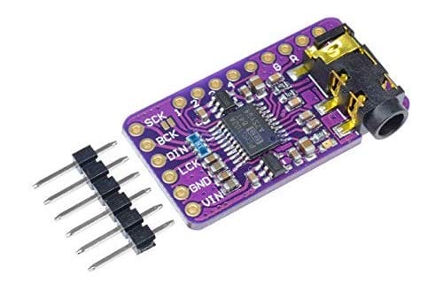
I am a big fan of these PCM5102A I2S DAC boards (3 for $15! affilliate) for playing around with audio synthesis, for example in this video about new `synthio` CircuitPython library or this repository about Mozzi Arduino synthesis. They have pretty high-quality audio output up to at least 16-bit @ 44.1kHz and separate out all the audio circuitry onto its own board with its own regulator! This makes it much less likely that your circuit’s noise will infect your audio. And the line out is strong enough to drive most headphones. The board itself is pretty small too at 29mm x 16mm.
Hooking the up PCM5102 board is pretty easy for the general case:
SCK – Gnd
BCK – I2S bit clock pin
DIN – I2S data pin
LCK – I2S word select pin
GND – Gnd
VIN – 3.3V
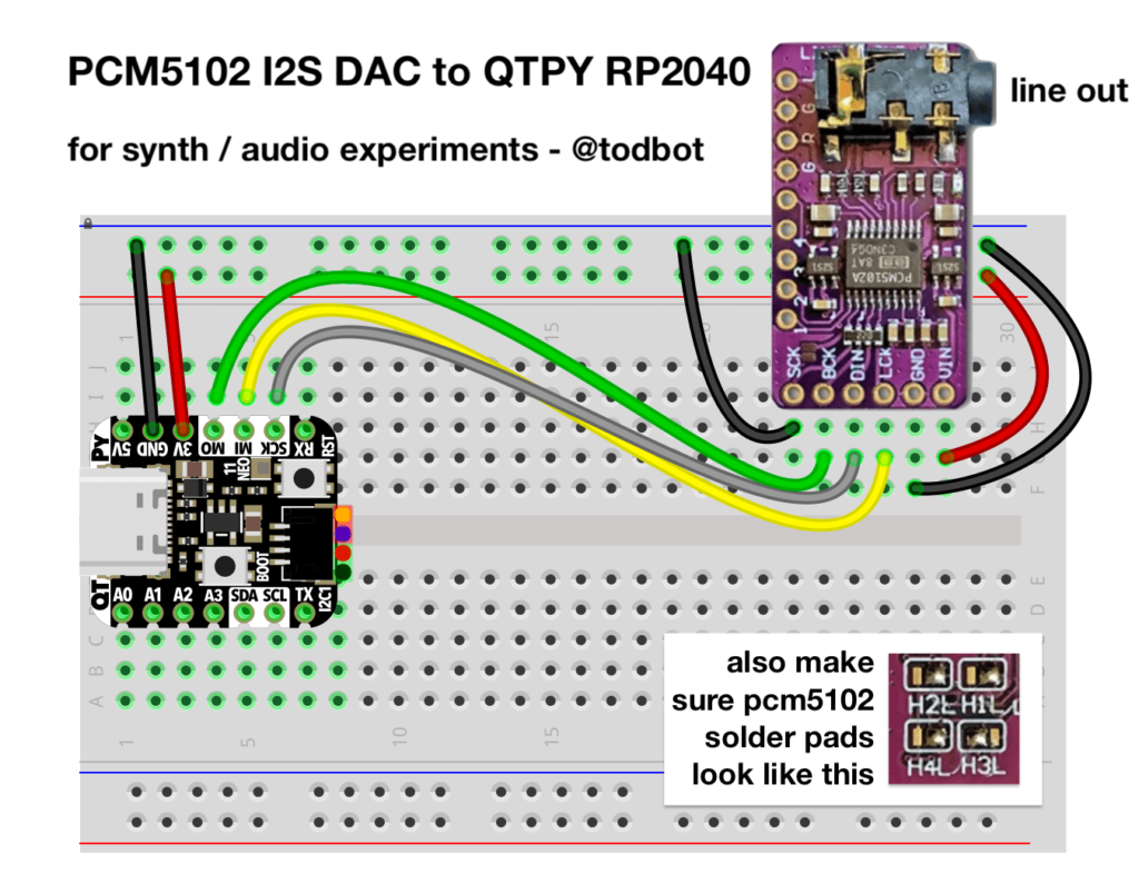
In the case of hooking up the PCM5102 board to an Adafruit QT Py RP2040, one way to do that is like this:
The corresponding CircuitPython setup using audiobusio.I2SOut() for the above wiring looks like:
Note that the back of the PCM5102 board has several solder jumpers to configure the chip. Most vendors will set these to a good default value, but verify if they match the above inset photo above or the yellow box in the photo below.
Most of the information I gleaned about the PCM5102 board I got from this macsbug blog post. It is very handy. From it is also the schematic for the PCM5102 board, included below:
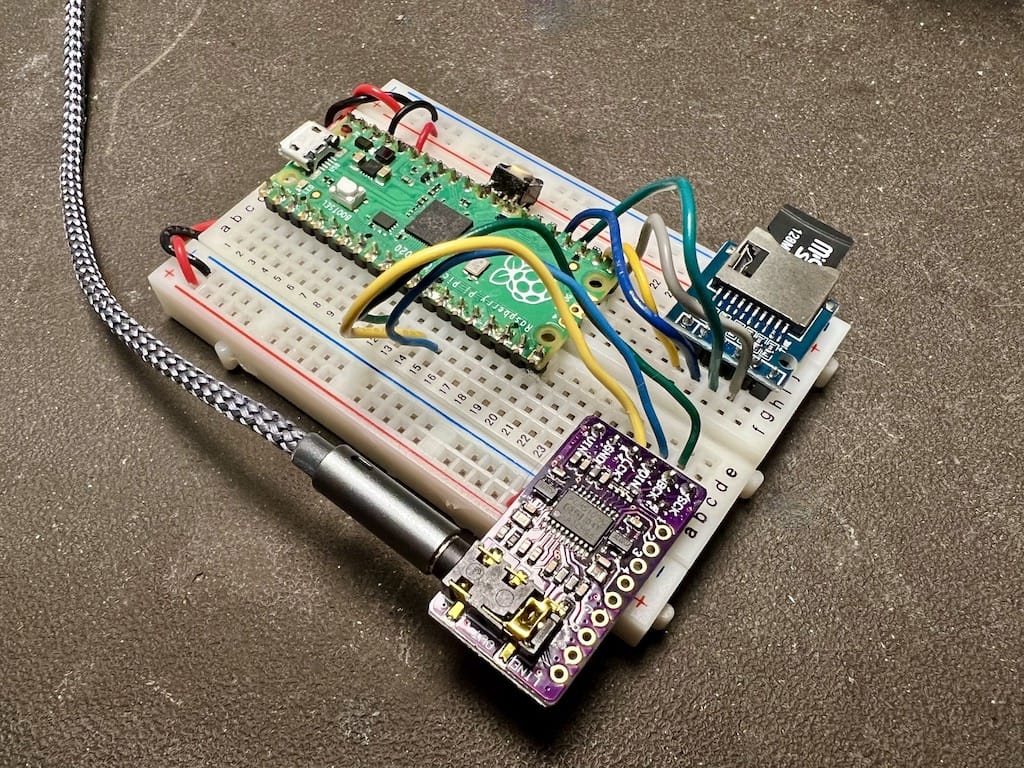
Here’s a complete SD-card based WAV player using a Raspberry Pi Pico and a PCM5102
And the CircuitPython code that plays WAVs off an SD card:
# i2s_sdcard_pico.py -- I2S Audio from SD Card on RP2040 Pico
# 20 May 2022 - @todbot / Tod Kurt

import time
import board, busio
import audiocore, audiomixer, audiobusio
import sdcardio, storage, os

# pin definitions
i2s_bclk = board.GP9  # BCK on PCM5102 (connect PCM5102 SCK pin to Gnd)
i2s_wsel = board.GP10 # LCK on PCM5102
i2s_data = board.GP11 # DIN on PCM5102
sd_mosi = board.GP19
sd_sck = board.GP18
sd_miso = board.GP16
sd_cs = board.GP17

# sd card setup
sd_spi = busio.SPI(clock=sd_sck, MOSI=sd_mosi, MISO=sd_miso)
sdcard = sdcardio.SDCard(sd_spi, sd_cs)
vfs = storage.VfsFat(sdcard)
storage.mount(vfs, "/sd")

# audio setup
audio = audiobusio. I2SOut(bit_clock=i2s_bclk, word_select=i2s_wsel, data=i2s_data)
mixer = audiomixer.Mixer(voice_count=1, sample_rate=22050, channel_count=1,
                         bits_per_sample=16, samples_signed=True)
audio.play(mixer) # attach mixer to audio playback

# find all WAV files on SD card
wav_fnames =[]
for filename in os.listdir('/sd'):
    if filename.lower().endswith('.wav') and not filename.startswith('.'):
        wav_fnames.append("/sd/"+filename)
wav_fnames.sort()  # sort alphanumerically for mixtape numbered order

print("found WAVs:")
for fname in wav_fnames:
    print("  ", fname)

while True:
    # play WAV file one after the other
    for fname in wav_fnames:
        print("playing WAV", fname)
        wave = audiocore.WaveFile(open(fname, "rb"))
        mixer.voice[0].play(wave, loop=False )
        time.sleep(3)  # let WAV play a bit
        mixer.voice[0].stop()
In many LED animations, you need to apply an operation to all LEDs as fast as possible. Often this is something like “fadeToBlackBy”, i.e. “dim all LEDs by a given amount”. There are some common effects you get by using “fadeToBlackBy” and one other action. For example: the Cylon effect is “Turn an LED on, Fade all LEDs toward black, Go to next LED, Repeat”. A simple firework simulation is “Turn on random LED, Fade all LEDs toward black, Repeat”.
Since I don’t come from a normal Python background, I’ve not used much Numpy. But I knew it was great for vector math. And I knew CircuitPython had a minimal version of Numpy called ulab it inherited from Micropython. Even though I’d seen the wonderful ulab learn guide that jepler did, the usefulness of numpy/ulab didn’t sink in. It was only when I was hacking on LED animation speedups did I re-stumble upon ulab. And am I glad I did.
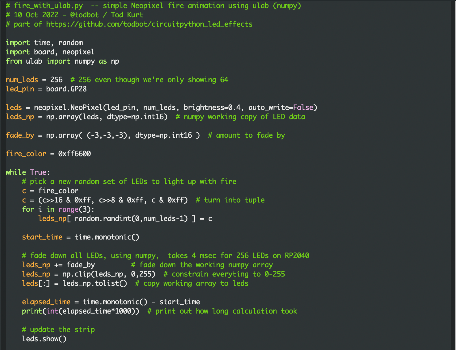
As a test with a simple fire animation (as optimized as I could make it in normal Python), the results with ulab are striking:
fire_no_ulab.py: ~40 milliseconds per frame for 256 LEDs on RP2040
The general technique is to create a “working copy” of the LED data in a ulab array, and use ulab functions as much as possible to modify that working copy. Then at the last possible moment, copy the working copy data to the real LEDs object. It only adds a few lines of code to existing solutions and you get access to all these cool ulab array functions for LED effects! For instance, to constrain all RGB values of all LEDs to 0-255, this is a single line in ulab: leds_np = np.clip(leds_np,0,255). And it further cements my belief that any time you’re doing a for-loop on a large list in Python, you’re probably doing it wrong. :-)
Screenshots of functionally identical code, before / after:
The video demo below shows the difference (also available on youtube). Each setup is identical, calculating for 256 LEDs even though only 64 are displayed. The “no ulab” case is perfectly usable if a bit choppy, but you lose ~36 milliseconds where you could be doing something else. (Like, for instance, these LED matrices are wired up in a serpentine pattern, so you need some math to unravel that if you want to draw shapes). The ulab version seems much smoother and more organic, at least to my eyes.
Did you know you can run multiple displays in CircuitPython? One way: wire up two displays in parallel.
There’s also true dual displays, more on that in a bit. For the above, here’s the wiring diagram and the code “gc9a01_hellocircles_compact.py”. Note how the second display is hooked up in parallel and the code just sees one display.
But what if you want each display to be independent?
CircuitPython is an amazing microcontroller programming platform, running on many different chips and boards while providing a consistent API. I’m pretty experienced with embedded development and Arduino, but have little Python knowledge. So for the last few years I’ve been using CircuitPython to teach myself Python. The results I’ve been logging via my QTPy Tricks and CircuitPython Tricks repos. CircuitPython is one of the most fun and useful tools in my toolkit now.
At the beginning of every year, the community reflects on CircuitPython and their plans for its future. This year the tag is “#CircuitPython2022“. Here are my (belated) plans / desires. My overall theme is: audio stuff!
eighties_arp – An arpeggio explorer for non-musicians and test bed for my “Arpy” arpeggio library
derpnote2 – A sound like THX “Deep Note” with 16 saw oscillators that converge to a chord
Arpy Arpeggiator Arduino library
Inside of the “eighties_arp” directory is “Arpy.h“. This is a small arpeggiator class that has some knowledge about music theory. An example that uses this is John Park’s Arcade Synth Controller. The library’s API is purposely very simple:
void loop() {
  // read knobs, set root_note and bpm
  arp.setRootNote( root_note );
  arp.setBPM( bpm );
  arp.update();
}