Little portable AVR development kit

Atmel AVR portable dev kit

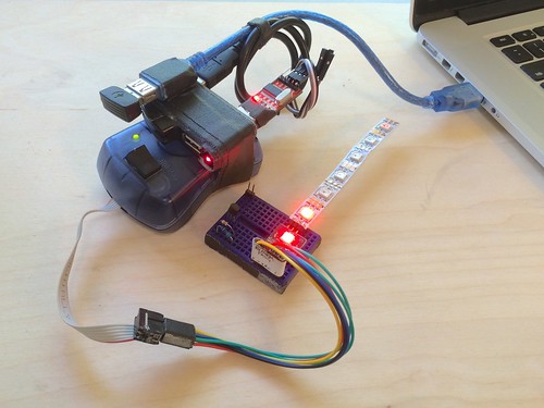
Recently a CrashSpace member asked about my little portable AVR dev platform. It’s small, compatible without avrdude hacks, and cheap enough to not worry about. Though it’s a gaffer-taped together setup, it’s served me well for about 10 years.  It’s in a go-bag about the size of my laptop’s power supply, so it’s often with me.  But people do sometimes look at me strangely when I whip this out at coffee shops. (but then I blink LEDs and all is forgiven)

The kit consists of:

  • AVRISP mkII programmer (w/ custom +5V switch on VTG (power to target))
  • USB hub, travel size 4-port
  • USB extension cable, 1 foot
  • Generic 3.3V/5V USB-to-serial adapter
  • Enough gaffers tape to bodge it all together

Just plug it all together and go.  The AVR ISP mkII is an official one from Atmel and is about $30. It looks like it may not be made any more, but there are many clones out there. The nice thing about the official one is that it works at 5V & 3V and has short-circuit protection.  I do wish the ISP protocol was faster though.  Compared to bootloaders, it’s around 5x slower. That adds up.

AVR Programmer VTG power

The VTG +5V switch add-on is super useful.  Normally ISP programmers don’t supply power to the target. (and shouldn’t, you don’t have to have a power supply fight)  But when doing exploratory development, having the programmer providing the power is really handy.  if you don’t want to mod your programmer, you could take an old USB cable, cut it up and run the +5V to your board.  If I were to do it again, I’d add some sort of current-limiting for those just-in-case oopses.

USB-to-serial

You don’t always need a serial port but when you do, you really do.  I usually keep this plugged in just in case, sort of like how I always keep a few LEDs & 1k resistors on hand.  Both are great for on-the-go debugging.

Programming adapter cables

For working with the strange, small boards I make, I have a collection adapters made from male-to-{male,female} jumpers that go from the AVRISP 6-pin connector to whatever I’m working on:
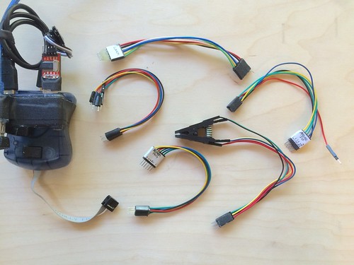
Atmel AVR portable dev kit


And when I work on PIC USB projects, I have a similar one for PIC.
 

Makerbot Replicator mods I’ve done

After two years, I think I have my Replicator (apparently the first one shipped) finally working reliably to produce >1 hour prints. Thank you @iandanforth for asking if I had a description of the mods I did and prompting me to write this.

The Replicator has been a very frustrating product. After a few out-of-the-box failures, it worked great for the first week and then rapidly deteriorated. And a few months later, the Replicator 2 was announced and support for my product rapidly evaporated. Many of the things I print are small and take <15 minutes to print, so I’ve been dealing with a <30% success rate of printing, or using other 3d printers. But I think I’ve been slowly iterating towards a reliable Replicator.

Things I have done thus far (in roughly chronological order):
* Replaced heated build plate since the original was very non-flat
* Replaced both thermocouples with parts from Makerbot
* Installed new extruder design (eliminates all filament feed issues)
* Installed Bottleworks aluminum replacement arms
* Went to three-point bed leveling by removing one of the four leveling nuts.

The heated build platform and thermocouple issues were just bad original parts from Makerbot. I still sometimes have issues with “Heating Failure #3 my extruders are losing temperature. Check my connections.” on the right extruder, but I think that’s because of either a small crack in the replacement thermocouple or it just coming loose. I’m strongly considering using this Wanhao Duplicator replacement thermocouple if the problem comes up again. At least they terminate the thermocouple with a lug instead of trusting the assembler won’t crack it when tightening.

Assuming the basic mechatronics of the printer work, the most critical fix is the new extruder design. If you’ve ever experienced your Replicator stopping extruding or only partially extruding, it’s because the original mechanism to push the filament against the extruder motor sucked. This change was so important that Makerbot themselves retrofitted all Replicator 2s with it.

MinimalMk8_preview_featured

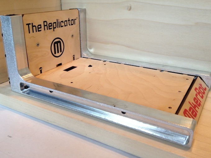
The next most critical mod is replacing those stupid plastic cantilever arms with something sturdier. Even at room temp, those arms exhibited considerable flex. Heat up the bed and the build plate would droop a few layers, causing so. many. failed prints. With the Bottleworks Aluminum arms, the bed is now rock solid.

bc-tech-elements-09

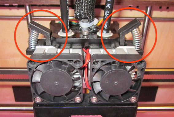
I’ve also printed some little helper parts like extruder fan guards and leveling knob covers

Here’s some lists of other popular upgrades:
– Makerbot Users list – “Popular non-printed upgrades”
– EEWeb Gary’s blog – “Makerbot Replicator upgrades

In general, be sure to poke around the Makerbot Users mailing list. It’s got useful tips and very knowledgable people.

From that and the (now discontinued) Makerbot Operators list, I’m just waiting for the day when the entire Replicator motherboard fries itself (another story, there are many) due to bad voltage regulator design. When that happens, not sure what I’ll do.

On the one hand, maybe get a steel Duplicator 4S, maybe a Lulzbot Taz 4 modded for 1.75mm filament, or maybe support the local guys and get a Bukobot.

blink(16) prototype is woody and awesome

[originally posted on ThingM blog]

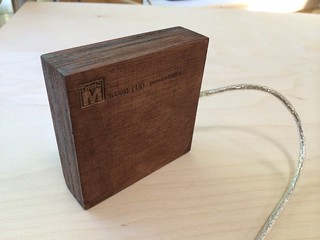
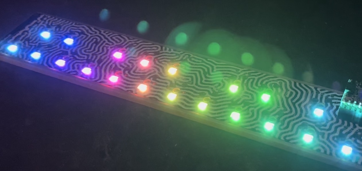
A few days ago ThingM friend Rusty, operator of the wonderful SomaFM, wondered if there would ever be a “blink(16)”: a blink(1) with a 4×4 grid of LEDs. Well it turns out that due to a secret feature of all blink(1) mk2s, it’s actually pretty easy to make, if you have some WS2812-style LED strip laying around.


blink16-somafm-500px

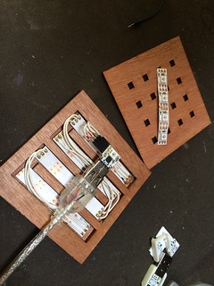
Making a blink(1) mk2 use 16 extra LEDs is pretty easy because it has a hidden 3-pin port for wiring up WS2812/NeoPixel-type LED strips.  In this photo, you can see the three holes: one each for Gnd, +5V, and data.

Below is a video showing it in action.  The two ‘blink1-tool’ commands used in the video are:

blink1-tool --random=1000  -l 18 -m 50 -t 50
blink1-tool --running  -l 18 -m 200 -t 200

Notice the “-l” option. Using this option, you can control a single LED in a blink(1) mk2. For instance, on a regular blink(1) mk2, you can do:

blink1-tool -l 1 --red
blink1-tool -l 2 --blue

to make the top LED red and the bottom one blue. For the “random” and “running” commands, the “-l” option means how many LEDs to use.

Some build photos from Flickr:
blink(16) blink(1) prototype
blink(16) prototype
blink(16) prototype
blink(16) prototype

Portable PIC16F145x Development Platform

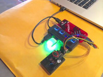
About a year ago, while I was developing the blink(1) mk2, I created both a PIC16F1455 development board and a little assemblage that was tiny enough to toss in my laptop bag but powerful enough to let me develop on the PIC.  I could now develop firmware in a coffeeshop!

Portable PIC16F1455 Development Platform

It consists of:

All taped together with double-stick foam tape.

The Sabrent USB hub is because it acts a partial goof-protector if I short USB power & ground and the per-port power switches make it easy to power-cycle the device I’m developing without unplugging-replugging.  The solderless breadboard is just big enough to support the addition of a few extra components.  And my dev board has female headers with male pins that stick into the breadboard, holding it securely place and making wiring to the dev board a snap.

If only MPLAB X & PICKit3 wasn’t so pokey for programming (it can take 15 seconds from the time you click “Upload”  to having your code running on the device)

Intro to the Arduino Entrepreneurial Ecosystem slides & audio

[originally posted on the ThingM blog]

The theme for the Caltech Entrepreneurs Forum’s November event was “The Internet of Things, Arduinos and the ‘Maker Entrepreneur’“.

caltech-entforum-talk-normal.001

My talk “Intro to the Arduino Entrepreneurial System” touched on all these topics. The entire event was a blast, including a wonderful talk about commercial making with open source by Quinn of QtechKnow.

Slides with notes and MP3 audio of the entire event are below.

Download MP3 of the entire Forum proceedings, including Tod’s talk.

MakerFaire Bay Area 2013 and my talk on blink(1) & Kickstarter

[originally posted on the ThingM blog]

makerfaire

Whew, MakerFaire Bay Area 2013 is over and it was astoundingly fun. Not only did we get to interact with so many people doing awesome things with ThingM products (like these BlinkM MinM earrings) but we got to show off a bunch of projects made with blink(1) and BlinkM-family stuff to thousands of new people. We heard tallies of 120,000 people showed up over the weekend, and we love seeing the concepts the Maker community inspires diffusing out into the larger world, as this LA Times article speaks to.

This year not only were we fortunate enough to have a ThingM table in the Maker Shed (Thank you Leah, Alex, Will, Carlyn, & Mike for helping staff it), but we also gave talks. Mike spoke about the future of manufacturing in a work filled with Maker-inspired tools and techniques, while I gave a talk on the process we went through to take blink(1) from an idea to Kickstarter to production.

Slides from my talk are below.