BlinkM Battery Pack HowTo

BlinkM Battery Pack: Done!

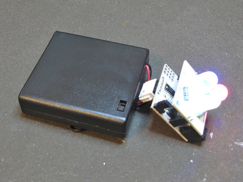
Make a long-lasting, rechargeable battery pack for your BlinkM MaxM, BlinkM, or BlinkM MinM using just pliers, no soldering!

BlinkMs are perfect for portable, stand-alone uses. There are many ways to hook a BlinkM to battery sources. Here’s one way that works for all BlinkMs.

BlinkM Battery Pack: Step 1: Get all the parts together

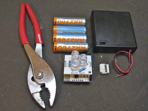
BlinkM Battery Pack: Step 1: Get all the parts together

Parts are:

BlinkM MaxM, BlinkM, or BlinkM MinM

– 4xAA battery holder with switch, like this Jameco one or Mouser one

– 4xAA NiMH batteries (not alkaline!)

– 2×8 IDC crimp connector (FCI 71600-308LF), from Digikey 609-3570-ND or Mouser 649-71600-308LF

Tools you’ll need:
– pliers with wide jaws to crimp
– cutters to trim excess wire

Continue reading “BlinkM Battery Pack HowTo”

ReflashBlinkM: Update your BlinkM’s firmware

All BlinkM-family devices can have their firmware updated. This makes them great for tiny development boards for ATtiny processors. ReflashBlinkM is an application that makes it easy to put back the original firmware or update a BlinkM to the latest firmware.

Previously you needed an AVR ISP programmer like the AVRISPmkII or the USBtinyISP. Thanks to the ArduinoISP sketch that ships with Arduino, if you have already have an Arduino, you can easily reflash your BlinkM with new firmware.

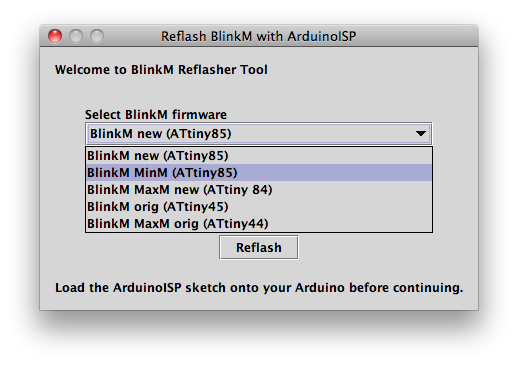
The ReflashBlinkM application is a tool for Mac OS X and Windows that uses ArduinoISP to help you reflash BlinkMs to their default firmware.

This is what it looks like:

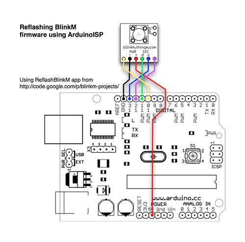
Here’s one way of hooking up a BlinkM to an ArduinoISP:

And here’s a video of a BlinkM MinM being reflashed:

For full instructions, see the ReflashBlinkM page in the blinkm-projects Google code site.

SoftI2CMaster: Add I2C to any Arduino pins

[update 20150128: changed links to SoftI2CMaster project on Github]

Ever wanted to use any pair of pins for I2C on Arduino, not just the dedicated pins on Analog 4 & 5? Me too, so I made a quick little Arduino library called “SoftI2CMaster”, available in the “blinkm-projects” Googlecode repository.

Get it here: SoftI2CMaster on github

It’s still a work in progress, but it can write data pretty successfully and do it over longer cables than normal.

For the VIMBY/Scion Hackerspace Challenge, I created an array of BlinkM MaxM-powered accent lights for the device we made. Because the I2C cable was longer than a few feet, the normal Wire library that BlinkM_funcs.h uses to communicate with BlinkMs couldn’t be used. This is because the Wire library assumes a perfect bus. If there is any noise or other bus problems, the Wire library will currently lock up. For the SoftI2CMaster library, I wanted it to be very tolerant, even lazy, about bus problems and also have more tunable timing to let you slow the bus down. Of course, you still need pull-up resistors on the two lines. I’ve found using 2.2k resistors to be good.

The SoftI2CMaster API follows Wire’s API pretty closely:

  • SoftI2CMaster(sdaPin,sclPin) — create an new SoftI2CMaster for the two pins specified
  • beginTransmission(address) — begin sending data
  • write(data) — send some data (byte or byte arrays)
  • endTransmission() — stop sending data

In use it looks something like this:

#include "SoftI2CMaster.h"
const byte sdaPin = 7;
const byte sclPin = 6;
SoftI2CMaster i2c = SoftI2CMaster( sdaPin,sclPin );

i2c.beginTransmission( 9 );  // write to address 9
i2c.write('c');
i2c.write(255);
i2c.write(0);
i2c.write(200);
i2c.endTransmission();

There is a simple demo for BlinkMs that this library currently lives in. It’s called “BlinkMSoftI2CDemo” and shows off a simplified BlinkM_funcs called “BlinkM_funcs_soft.h“. The entirely of BlinkMSoftI2CDemo is shown below.

const byte sdaPin = 7;  // digital pin 7 wired to 'd' on BlinkM
const byte sclPin = 6;  // digital pin 6 wired to 'c' on BlinkM

#include "SoftI2CMaster.h"
SoftI2CMaster i2c = SoftI2CMaster( sdaPin,sclPin );

// must define "i2c" before including BlinkM_funcs_soft.h
#include "BlinkM_funcs_soft.h"

byte blinkm_addr = 9;

//
void setup()
{
  Serial.begin( 19200 );
  Serial.println("BlinkMSoftI2CDemo");

  BlinkM_off(0);

  for( int i=0; i< 100; i++ ) {  // flash the blinkms
    BlinkM_setRGB( blinkm_addr, 255,255,255 );
    delay(10);
    BlinkM_setRGB( blinkm_addr, 0,0,0 );
    delay(10);
  }
}

void loop()
{
  byte r = random(255);
  byte g = random(255);
  byte b = random(255);
  
  BlinkM_setRGB( blinkm_addr, r,g,b );
  delay(10);
  BlinkM_fadeToRGB( blinkm_addr, 0,0,0 );
  delay(1000);
}

void BlinkM_off(byte addr)
{
  BlinkM_stopScript( addr );
  BlinkM_setFadeSpeed(addr,20);
  BlinkM_setRGB(addr, 0,0,0 );
}

Hacking USB HID for Easy Tethered Ubicomp

At this years Sketching in Hardware conference, I gave a talk on the general approach I used to create LinkM, ThingM’s USB-to-I2C adapter for programming and controlling BlinkMs. I called it “Hacking USB HID for Easy Tethered Ubicomp” (4.8MB PDF) to give it a form that fit within some of the larger issues I’ve been dealing with in creating easily usable ubiquitous computing devices.

USB has many different (and confusing) aspects to it. I’ve long advocated the creation of a set of libraries and patterns to make “driverless” USB a reality. A sort of training wheels for USB. At the time I called this USB on Rails”, poking fun at RoR.

To me the key to this ease-of-use was the HID class in USB. No driver is needed when plugging in something like a mouse or keyboard. Other built-in device class drivers include CDC (modems), Mass storage, audio (headset), and video (webcam).

While researching HID, trying to make LinkM a “USB on Rails” project, I found that the biggest hurdle was a consistent host-side USB API that would let one write one set of code that could easily be ported to Mac OS X, Windows, and Linux. Libusb works well enough for Unix-like OSes like Linux and Mac OS X, but the Windows variant libusb-win32 required a driver install. So I put HID away.

For many months I investigated using CDC instead of HID because it maps down to a serial port on modern operating systems. Unfortunately, CDC has two main problems. For the “serial port emulation” mode, mapping to serial port semantics is problematic for a USB device that can be removed at will. If a device is removed while it is still “connected”, the OS and application can get confused or crash. Also, the CDC driver implementation seems brittle on Mac OS X. Some CDC devices can work fine, others wouldn’t. I can see now why FTDI and similar vendors use a custom driver for their USB-to-serial chips.

When looking back into HID after the frustration with CDC, I discovered that V-USB, the software-only USB firmware stack for AVR microcontrollers, had two interesting HID-based projects in them with a cross-platform host-side library for talking HID. The first was BootloadHID, a HID-based bootloader, and the second was “hid-data”, one of the examples. And there was a nice discussion of the platform differences on the V-USB wiki.

With that, I took both of those projects, generalized them slightly, then specialized them for LinkM and made them the core of the LinkM project. You can view the resulting source at the LinkM Googlecode project.

ThingM at Maker Faire 2010

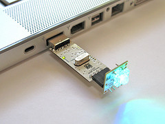
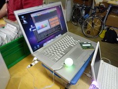
My company ThingM had an official presence at Maker Faire this year. We were showing off the BlinkM line, including the new BlinkM MinM and the LinkM USB BlinkM controller. It was a lot of fun. And packed!

ThingM at Maker Faire 2010
(click any photo to go to larger version on Flickr)

We were in the Maker Shed building, right underneath the Arduino banner, so we got lots of awesome questions about Arduino. The most common: “So I just picked up this thing that says ‘works with Arduino’…well, what *is* Arduino?” It was so great to see so many people interested in building their own gizmos.

ThingM at Maker Faire 2010 ThingM at Maker Faire 2010

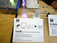
By far the most fun demo we had was TwitM, the Twitter-controlled BlinkM. Using LinkM, a couple BlinkMs, and a Processing sketch, I had it so anyone who tweeted anything with the keyword “makerfaire” made one BlinkM flash. If you tweeted “blinkm colorname”, where colorname was any color in the X11 color names or a hex color code RRGGBB, the other BlinkM would turn that color. Because of the streaming Twitter API, these changes happened instantly; it was really something to see.

ThingM at Maker Faire 2010 ThingM at Maker Faire 2010

Kim and Mike made up some really nice “walltext” describing the various demos we had up.

ThingM at Maker Faire 2010 ThingM at Maker Faire 2010

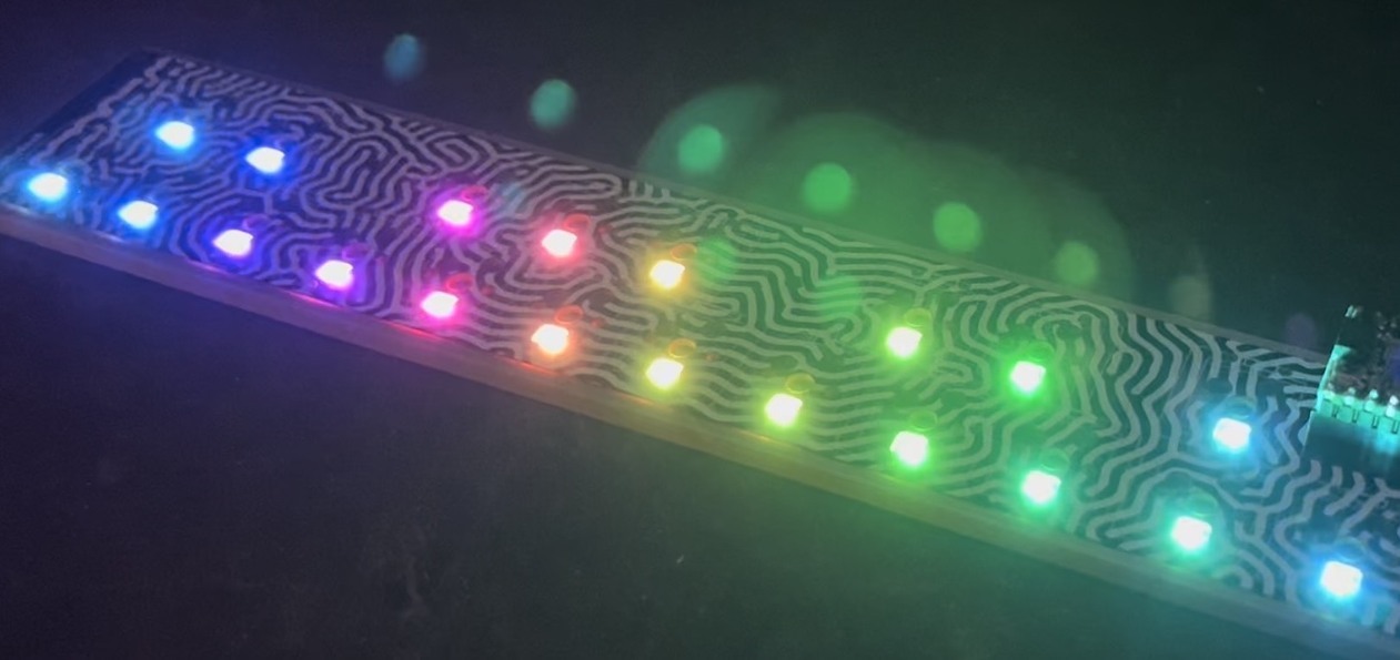
A big hit was MaxM controlling RGB LED flexible circuit tape, using the same techniques I used for the Crystal Monster.

ThingM at Maker Faire 2010 ThingM at Maker Faire 2010

This was about regular busy at the Faire. There were many times when it got way more packed.

Momentary Button as On/Off Toggle using 555

(as a few had noticed, I had an error in the schematic shown. It’s been updated, thanks!)

A recent question from a friend who made a really cool BlinkM hoodie was: How can you turn a momentary button press into an on/off toggle?

There are tons of ways to do this if you like getting into electronics. Most all work off of some flip-flop like principle. And while I could have suggested a true flip-flop chip, I thought it would be cooler if you could use a 555 timer chip (which contains a single flip-flop and a couple of comparators). After scouring my childhood collection of Forrest Mims electronics books and a few 555 timer devoted websites (two of the best I found were: http://www.bowdenshobbycircuits.info/ & http://www.kpsec.freeuk.com/555timer.htm), I cobbled together the following circuit based off a few almost-what-I-wanted examples.

This is what it looks like in use:

The schematic is pretty straightforward, but does use a bit of feedback trickery to get the toggle functionality:
On/off toggle switch from a momentary switch using 555
(old incorrect version here)

The parts cost is pretty low. The 555 timer chip can be had for about $0.43, the 2N3904 transistor for ~$0.40, and various resistors & capacitors are essentially free if you have them.

The circuit has 3 external two-pin connections: 5V&Gnd, button input, and the two pins of the thing to switch. In this case, the switched thing is a power supply to a BlinkM.

By changing the transistor to a beefier one, you can switch much larger loads. The little 2N3904 transistor in there now can switch around 200mA, but a bigger NPN or FET transistor and you could switch a few amps.

It can be made pretty small on a tiny breadboard (courtesy of FunGizmos.com) like this:
Simple on/off toggle from a momentary switch

It’s not the greatest for battery-powered applications. When “off” it draws about 4-6mA, depending on the brand of 555 timer chip you use. When on it draws that plus whatever power the switched device draws. Best to put a proper power switch on the battery pack to eliminate this quiescent drain.
On/off toggle switch from a momentary switch using 555

I2CScanner: Arduino as I2C bus scanner

[2014-May-9: updated to work with Arduino 1.0 and moved into github]

One of the challenges of working with I2C (aka “two-wire” or “TWI” or “Wire”) devices is knowing the I2C address of the device. Older devices have a fixed address, or a “choose one-of-four” approach. But newer I2C devices have fully programmable addresses, leading to cases of not knowing what address a device is at.

Fortunately, there’s a technique one can use to “scan” an I2C bus and determine these addresses. Conceptually it’s very similar to a network “ping”. Below is an Arduino sketch “I2CScanner.pde” that turns an Arduino into an I2C bus scanner.

I2CScanner.ino — Turn Arduino into I2C bus scanner (github repo)

When loaded up on an Arduino, the sketch will immediately scan the I2C network, showing which addresses are responding.
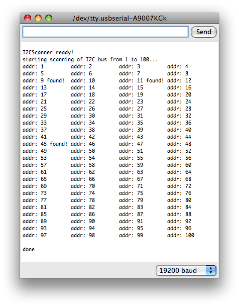
i2cscanner-out

For example, the above output is from an I2C bus with four slave devices on it (one BlinkM MaxM, three regular BlinkMs).
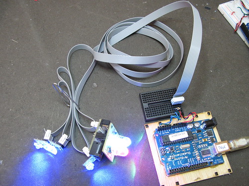
I2CScanner with BlinkMs
(Notice the 2 pull-up resistors on SDA & SCL. This is needed for longer bus lengths)

One thing to notice about the I2CScanner output is that although there are four devices on the bus, only three addresses were detected. This is because unlike IP networks and “ping”, you can’t tell if two devices have the same address. They’ll both respond to commands sent to them just fine, you just can’t read back data from them.

How it works

In I2C, the first byte transmitted/written by the master to a slave is the address of the slave. If there is a slave at that address, the slave will signal the I2C bus, otherwise it leaves it alone. We can use this to implement a bus scanner.

The Arduino “Wire” library utilizes a set of C functions called “twi.c”. One of those functions is “twi_writeTo()”. This function is used to both send the address of the slave down the bus and also to write data to slaves. It returns 0 if it was able to successfully transmit a byte or non-zero if it couldn’t. Since the very first write to a slave is its address, a very simple bus scanner using it would be:

void scanI2CBus(byte from_addr, byte to_addr) {
  byte data = 0; // not used, just a ptr to feed to twi_writeTo()
  for( byte addr = from_addr; addr < = to_addr; addr++ ) {
    byte rc = twi_writeTo(addr, &data, 0, 1, 0);
    if( rc == 0 ) {
      Serial.printl("device found at address "); 
      Serial.println(addr,DEC);
    }
  }
}

In the I2CScanner sketch, this function is extended a bit to support a callback function. The callback function is called with the result of every address scan. In I2CScanner, this callback function is called “scanFunc()” and just prints out “found!” or nothing, but it could be modified to do more complex tasks like doing additional I2C transactions to figure out what kind of device it is, or setting all the devices to a known state, etc.