Arduino-serial: C code to talk to Arduino

[NOTE! arduino-serial has been greatly updated. See the “Arduino-serial: updated!” post for details]

The Arduino’s USB port is actually a serial port in disguise. To your computer it appears as a ‘virtual’ serial port. This is good news if you want to write custom code on your computer to talk with the Arduino, as talking to serial ports is a well-solved problem. (Unfortunately, so well-solved that there’s many ways of solving it.)

On the Arduino forum there’s been a few requests for some example C code of how to talk to Arduino. The nice thing about standard POSIX C code is that it works on every computer (Mac/Linux/PC) and doesn’t require any extra libraries (like what Java and Python need). The bad thing about C is that it can be pretty incomprehensible.

Here is arduino-serial.c (github for full source), a command-line C program that shows how to send data to and receive data from an Arduino board. It attempts to be as simple as possible while being complete enough in the port configuration to let you send and receive arbitrary binary data, not just ASCII. It’s not a great example of C coding, but from it you should be able to glean enough tricks to write your own stuff.

Usage

laptop% ./arduino-serial
Usage: arduino-serial -b <bps> -p <serialport> [OPTIONS]
Options:
  -h, --help                 Print this help message
  -b, --baud=baudrate        Baudrate (bps) of Arduino (default 9600)
  -p, --port=serialport      Serial port Arduino is connected to
  -s, --send=string          Send string to Arduino
  -S, --sendline=string      Send string with newline to Arduino
  -r, --receive              Receive string from Arduino & print it out
  -n  --num=num              Send a number as a single byte
  -F  --flush                Flush serial port buffers for fresh reading
  -d  --delay=millis         Delay for specified milliseconds
  -e  --eolchar=char         Specify EOL char for reads (default '\n')
  -t  --timeout=millis       Timeout for reads in millisecs (default 5000)
  -q  --quiet                Don't print out as much info

Note: Order is important. Set '-b' baudrate before opening port'-p'.
      Used to make series of actions: '-d 2000 -s hello -d 100 -r'
      means 'wait 2secs, send 'hello', wait 100msec, get reply'

Example Use

Send the single ASCII character “6” to Arduino

laptop% ./arduino-serial -b 9600 -p /dev/tty.usbserial -s 6

This would cause the Arduino to blink 6 times if you’re using the serial_read_blink.pde sketch from Spooky Arduino.

Send the string “furby” to Arduino

laptop% ./arduino-serial -b 9600 -p /dev/cu.usbserial -s furby

Receive data from Arduino

laptop% ./arduino-serial -b 9600 -p /dev/cu.usbserial -r
read: 15 Hello world!

The output is what you would expect if you were running the serial_hello_world.pde sketch from Spooky Arduino.

Send ASCII string “get” to Arduino and receive result

laptop% ./arduino-serial -b 9600 -p /dev/cu.usbserial -s get -r
read: d=0

Internals

There are three interesting functions that show how to implement talking to serial ports in C:

  • int serialport_init(const char* serialport, int baud)
    — given a serial port name and a speed, return a file descriptor to the open serial port.
  • int serialport_write(int fd, const char* str)
    — write out a string on the given a serial port file descriptor
  • int serialport_read_until(int fd, char* buf, char until, int timeout)
    — read from serial port into a buffer until a given character is received or timeout reached

You can and should write improved versions of the read and write functions that better match your application.

Update 8 Dec 2006:
Justin McBride sent in a patch because it turns out Linux’s termios.h doesn’t define B14400 & B28800. I’ve updated arduino-serial.c to include the patch, but commented out for now. No one uses those baudrates much anyway. :) If you need them, uncomment the additions out, or better yet, download Justin’s tarball that includes the changes and a Makefile to auto-detect your platform.

Update 26 Dec 2007:
Added ability to sent binary bytes with the ‘-n’ flag.
Added a delay option so you can open a port, wait a bit, then send data. This is useful when using an Arduino Diecimila which resets on serial port open.

Update 29 Apr 2013:
I apologize to everyone who has commented on this post but who hasn’t received a reply. This code has had a much longer life than I expected and it was hard to get back to it to fix some of its obvious deficiencies.

I did finally get back to it (but not the comments). I’ve rewritten arduino-serial a bit and added some new options. Hopefully this will address many of the issues people have had. You can read about the changes in the “Arduino-serial: updated!” post.

Also, arduino-serial now lives on Github at:
   https://github.com/todbot/arduino-serial   
Please post issues and patches there. Thanks!
Spooky Arduino Projects #4 – Musical Arduino

spooky arduino projectsarduino class merit badge

The notes for the fourth and final class are up on the Spooky Arduino class page. At the end of the class, Mark of Machine Project bestowed upon each of the students a merit badge. It was great. Click above for a larger view of the badge.

Arduino MIDI Drum Kit and Spooky Sound Trigger

Here’s a quick project using techniques from this week’s class that turns an Arduino board and a few buttons and piezos into a MIDI drum kit or scary sound trigger. Hide piezo sensors around the house during your Halloween party to trigger scary sounds when people walk around!

Hardware

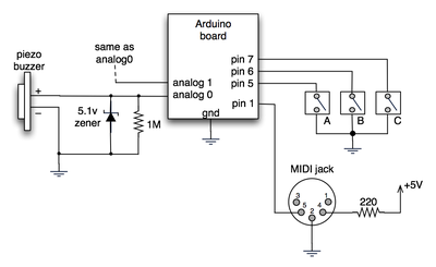
The hardware is an Arduino board with a MIDI jack, a few buttons, and two piezos attached to it. It runs off of a 9V battery.

arduino midi schematic

(Note: depending on what kind of MIDI connector you’re usign (jack or cut-off cable), you may need to swap the connections to MIDI pins 4 & 5).

For the piezo input, the 1M resistor is to bleed off the voltage generated by the piezo when it is struck. The 5.1v zener diode is there to insure any large voltages don’t make it into the Arduino and blow it out.

Arduino code

The code has a few tricks that may not be immediately obvious. First is that to implement a MIDI interface, all you really need is the ability to send serial data at 31,250 bps. This is easily done with “Serial.begin(31250)“. Once that is done, a complete three-byte MIDI note-on message can be sent with three “Serial.print(val,BYTE)” commands.

The next tricky bit is that the switches in the above schematic don’t need pull-up resistors. This is because the internal pull-ups in Arduino’s AVR chip are turned on with a “digitalWrite(pin,HIGH)“. This may seem counter-intuitive, doing a digitalWrite() on an input pin, but it’s how the AVR works. The benefit is that you no longer need a resistor to +5V and the effort to wire up each additional button is much lower.

The final trick is measuring impact force on a piezo. When piezo elements are struck, their output voltage rings, sort of like a bell. Kind of like this:
piezo whack!

By measuring the time it takes for that first big jolt to cross a threshold, you can get an idea as how big the force was. In the code this is represented by reading the analog value and if it’s over the threshold, wait until it drops down again, counting all the while. When I’ve done this before, I used an input opamp to convert the analog signal to digital (thus doing thresholding in the analog domain) and then used interrupts to get very accurate force measurements.

Arduino code: midi_drum_kit

References

DIY Ambient Orb with Arduino, update

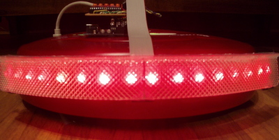
There’s been some confusion as to whether or not the DIY RGB orb presented in the last post was actually connected to a computer and receving color data from it. Here’s a video that more accurately depicts what’s going on and all the code used to create it.

Hardware

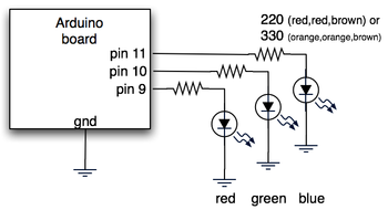
The hardware is just an Arduino board connected via USB to a laptop. The Arduino appears as a serial device to the computer. On the Arduino board, three LEDs (red,green,blue) are mounted directly to the Arduino board using a prototyping shield like this DIY one. The schematic is quite simple:
rgb_led_schematic.png

Arduino code

The code sketch running on the Arduino board is a slightly modified version of the one presented in the last Spooky Arduino class. Instead of parsing single color values over the serial port, it expects a full RGB color value in standard web format of “#RRGGBB” (white is “#ffffff”, blue is “#0000ff”, and so on). The sketch parses that seven character string into three bytes: one each for the brightness values of the red, green and blue LEDs.

Arduino code: serial_rgb_led_too.pde

Processing code

To bridge between the Arduino and the Net, a small Processing sketch was created that uses the standard Java HTTPURLConnection class to fetch a web page (really, a text file on a web server) containing a line with a color value in the format “#RRGGBB”. The sketch parses the color value, sends the value out to the Arduino orb using the Processing Serial library, and then sets its own background color to match. Because I’ve set the framerate of the sketch to 1 fps, it takes a second for the background to match the orb. I did this on purpose so I could get a sense of the color as the orb reproduces it before seeing it as it truly is. I was surprised how well the two tended to match!

Processing code: http_rgb_led.pde