For this project, I wanted a device that wasn’t an absolute mapping of position to color amount. I didn’t want a strict teaching device, but more of a fun color exploratory toy, able to be spun like mad by kids.
Rotary encoders are used to measure rotational amount and direction. You can find them in “infinite rotation” knobs, computer mice, robots, and lots of other things. They’re a good solution for user interface input devices when you want to make relative adjustments to a value, rather than absolute positioning (where a pot would work well). Wikipedia’s “rotary encoder” entry is a pretty good explanation of the various types of encoders. Wikipedia mentions absolute positioning encoders, a much rarer and more expensive type. Most all rotary encoders you’ll encounter are the relative positioning type. There are two main classes of relative rotary encoder implementations: mechanical and optical. Both make electrical signals when the encoder is rotated. Mechanical uses tiny electrical wipers to produce them. An optical encoder uses an optical interrupter, consisting of a light beam and light sensor.

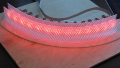
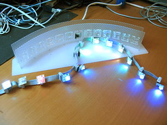
I experimented with mechanical encoders but they had a lot of friction and their pulses-per-revolution were fairly low (12-24). I wanted a low-friction, high-resolution encoder. For low-friction this meant an optical encoder, and for high-resolution this meant a large encoder disk (since I was using fairly large optical interrupters).

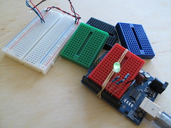
To sense the slots in the disk, standard H21A1 optical interrupters are used. These optical interrupters are simply an IR LED (”emitter”) and an IR phototransistor (”detector”) in a single package, pointing at each other. Breaking or unbreaking the beam creates a signal you can measure. If you hook them up, you can see the IR LED using a digital camera:

You can see the “E” and “D” markings for “emitter” and “detector” above.
A single interrupter can measure speed of rotation by counting pulses. It can’t measure direction of rotation. But by using two interrupters and “quadrature encoding” (two output signals offset by 90º), you can measure both. The spacing between the slots, the spacing between the interrupters, and the aperture width of the LED emitter are interrelated in order to get proper quadrature output. Hopefully I’ll have a subsequent blog post describing this in more detail. :) To decode quadrature encoding, pick one of the two signals (call them “A” and “B”): when A goes HIGH, measure B. The value of B gives the direction of rotation. By counting the number of times A goes HIGH, you know how much rotation is happening. In the diagram below, follow the two signals as rotation happens either clockwise (to the right in the diagram) or counterclockwise (to the left)

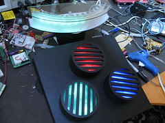
Building the Knobs
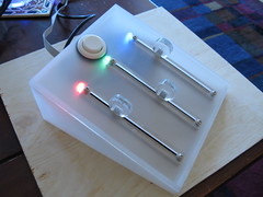
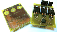
The knobs are constructed out of PVC drainage caps, laser cut acrylic for hubs & diffusers, rollerblade bearings to give a smooth spin, 5/16″ bolts to act as axles, hot glue to put it all together, and a plywood base. The black, slightly rubbery texture was from the spray-on form of PlastiDip.

My good friend Ben Franco helped prototype many iterations of the physical design of the knobs, until we came upon the final result. He was the one who recognized that the diameter of 5/16″ nuts was just perfect enough to grasp the inner ring of a rollerblade bearing. So a 5/16″ bolt through the center of the bearing becomes the axle and the outer ring of the bearing can be attached to a stationary base, giving a smoothly spinning knob.
Rotary encoder Arduino code
When reading rotary encoders, it’s useful to think of the two signals coming out of it as a “clock” and a “data” signal. It doesn’t matter which one you treat as which, as it’s the interrelationship between the two that matters. Usually you’d use interrupts to handle reading encoders because it makes it very simple: on interrupt of the “clock” signal, read the “data” signal, and its value gives you the rotation direction. On Arduino we’ve only got one interrupt and three knobs, so polling is easier. I started with the a really good Arduino playground rotary encoder polling example and then went from there.
The relevant parts of the BlinkMCylon code for dealing with rotary encoders is below. It’s almost encapsulated enough to be a library. The “knobs” data structure contains a list of “knob” data structures, which in turn is just a holder for which pins the knob is connected to, what the last value was of that knob’s clock pin, and its current rotation value.
The “knobs_init()” function sets up the pins correctly, and by calling “knobs_poll()” as fast as possible, you can read many knobs fairly accurately.
typedef struct _knob {
    uint8_t clkpin; uint8_t datpin; uint8_t clklast; uint8_t val;
} knob;
knob knobs[num_knobs] = {
    { 2,3, 0, 0},    // first knob on pins 2 & 3
    { 4,5, 0, 0},    // second knob on pins 4 & 5
    { 6,7, 0, 0},    // third knob on pins 6 & 7
};

static void knobs_init(void)
{
    for( int i=0; i<num_knobs ; i++ ) {
        pinMode( knobs[i].clkpin, INPUT );
        pinMode( knobs[i].datpin, INPUT );
        // turn on internal pullup resistors so we don't need external ones
	digitalWrite( knobs[i].clkpin, HIGH);
        digitalWrite( knobs[i].datpin, HIGH);
    }
}

// this function must be called as quickly and as regularly as possible
static void knobs_poll(void)
{
    byte c,d;  // holder for readings
    for( byte i=0; i<num_knobs; i++ ) {
	knob k = knobs[i];           // get a knob
	c = digitalRead( k.clkpin ); // read its pins
	d = digitalRead( k.datpin );
	if( c != k.clklast  ) {      // look for clk line transition
            d = c^d;                   // xor gives us direction
	    if( d ) k.val++;           // non-zero means clockwise rotation
	    else k.val--;              // zero means counter-clockwise rotation
	    k.clklast = c;             // save the clk pin's state
            knobs[i] = k;              // save our changes
	}
    }
}
Resources & Links
Other info: