Two-Wire NeoPixel WS2812 LEDs

Neopixel LEDs with only two wires?! Just data & ground? What kind of magic is this?

This is my take on this hack that Parallax Propeller forum user “Tubular” posted about in 2014 (!)

The trick is that the data line is carrying power, and a capacitor and Schottky diode are on the strip to separate out the data from the power. The capacitor holds the charge (mostly) for the LEDs as the WS2812 data line goes LOW and the diode keeps the capacitor’s voltage from interfering with the data line.
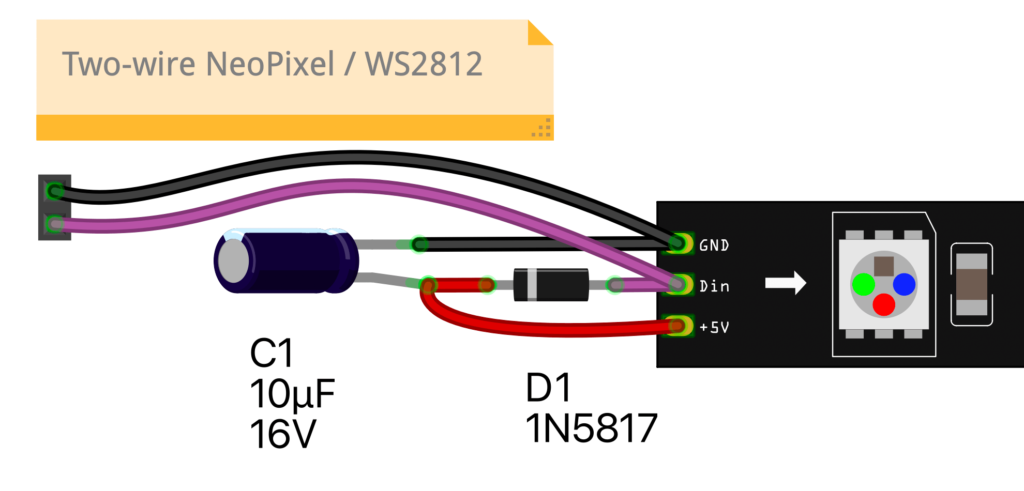
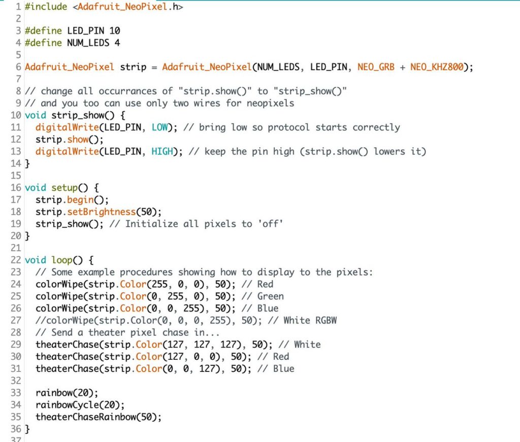
To keep the strip powered, make sure to set the data line HIGH after every frame of data sent. This keeps the strip powered. This technique works with most any WS2812 / NeoPixel library on Arduino or CircuitPython. If you want to try two-wire NeoPixels out in Arduino, one way is to change your “strip.show()” (if using Adafruit_NeoPixel library) to the function “strip_show()” shown below. The example a lightly-edited version of Adafruit_NeoPixel’s “strandtest_wheel”.
For CircuitPython, check out this gist.
QTPy-knob: Simple USB knob w/ CircuitPython

I like minimal solutions to problems. I was playing with a CircuitPython-enabled QT Py on a breadboard with and a rotary encoder and I ended up making a USB knob, like many others have done before. But I realized: waitaminute, I can literally just plug the encoder directly onto the QT Py…

Thus was born the QTPy-knob. It’s one of the simplest USB knobs I’ve come across and it’s because the happenstance that a rotary encoder can usefully be plugged directly into a QT Py board and that CircuitPython is so powerful now it’s just a few lines to go from rotary encoder pulses to sending arbitrary USB keyboard or mouse commands.

I really liked the Griffin PowerMate from over a decade ago, so I decided to design a 3d-printable enclosure that echos the design of the PowerMate, but that works with the restrictions of the QTPy+encoder stackup and a Neopixel ring. The result is pretty good I think.

All design files are in the qtpy-knob github repo.

The code is must easier now than the media-dial project I started cribbing from. This is due to the fact that CircuitPython now has native support for rotary encoders and this knob is trying to do much less than media-dial project.

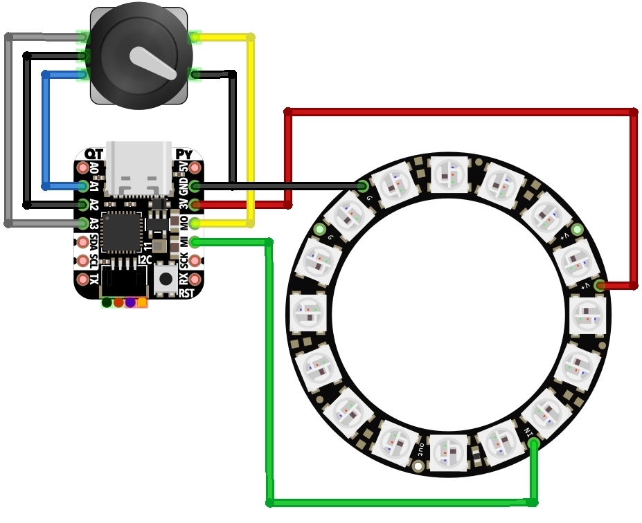
The electrical wiring is virtually non-existent, only needing three wires if you elect to add a Neopixel ring.

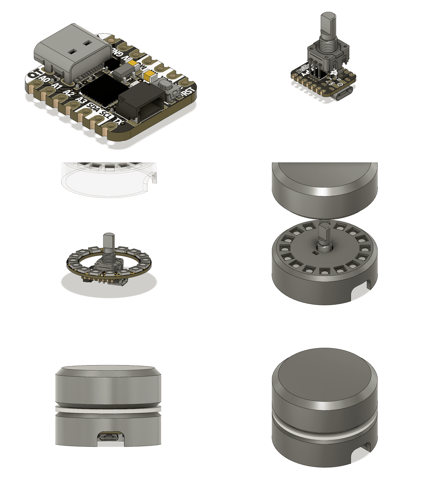
The assembly is described in the video above a bit, but you can also see what’s up in this CAD animation (thanks to the Adafruit_CAD_Parts repo for making the enclosure design easier)

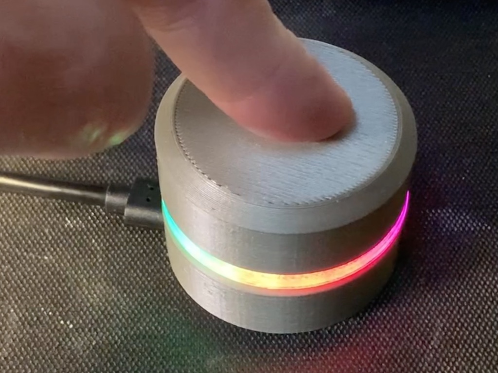
The result with opaque plastic and clear LED diffuser ends up looking pretty cool.

Get HID Report Descriptors with “win-hid-dump” & “mac-hid-dump”

I help support the USB HID projects hidapi and node-hid. One of the aspects of HID that isn’t clear is that HID devices transmit and receive data with “reports”, fixed-size data packets. What reports a device responds to is described by the HID Report Descriptor it hands to the OS. The OS then only permits those reports to be sent and received. This descriptor is different from the USB Config & Device Descriptors Those two are easily discoverable using standard system tools, but for whatever reason, getting HID Report Descriptors is much harder.

To address this, I’ve created two tools: win-hid-dump and mac-hid-dump from code snippets around the Net. They are akin to simplified versions of usbhid-dump for Linux. They print the HID Report Descriptors of the HID devices currently connected and the output can be parsed by things like https://eleccelerator.com/usbdescreqparser/

The tool repos with pre-compiled releases:

I’ve found many of the issues I have in supporting node-hid is getting people to understand that you need to know the type and sizes of the reports you want. Hopefully they’ll be useful to others as well. Let me know if you have any issues with them.

The output looks something like:

tod@demo ~/Downloads/mac-hid-dump$ ./mac-hid-dump
mac-hid-dump:
16C0 0486:  - Teensyduino RawHID Device
DESCRIPTOR:
  06  c9  ff  09  04  a1  5c  75  08  15  00  26  ff  00  95  40
  09  75  81  02  95  20  09  76  91  02  95  04  09  76  b1  02
  c0
  (33 bytes)
16C0 0486:  - Teensyduino RawHID Device
DESCRIPTOR:
  06  ab  ff  0a  00  02  a1  01  75  08  15  00  26  ff  00  95
  40  09  01  81  02  95  40  09  02  91  02  c0
  (28 bytes)
27B8 01ED: ThingM - blink(1) mk3
DESCRIPTOR:
  06  ab  ff  0a  00  20  a1  01  15  00  26  ff  00  75  08  85
  01  95  08  09  00  b2  02  01  75  08  85  02  95  3c  09  00
  b2  02  01  c0
  (36 bytes)
tod@demo ~/Downloads/mac-hid-dump$

DIY Neopixel / WS2812 Development Kit

If you are like me, you play around with Neopixel / WS2812-style LEDs a lot. Normally I solder my own custom-connectors and don’t use the ones that come with the reels I buy. But since we’ve been playing around with WS2812-compatible Xmas lights, I decided to make a “Neopixel Dev Kit” for easier experimenting with different LEDs and different ways of powering them. Most LED reels come with a 3-pin JST SM socket (female) connector installed with also maybe a 2.1mm DC barrel connector to inject power (see reel picture below). They’ll also throw in a pigtail JST SM plug (male) connector to attach to your controller. So I standardized on this. The kit as shown consists of (from bottom to top):

  • 3-pin JST SM socket (female) added to weird new WS2812-compatible Xmas lights
  • Known-good USB-powered WS2812 controller from those lights, rewired with JST SM plug
  • Standard 3-pin JST SM plug to JST SM socket, with 2.1mm DC barrel connector power injector
  • 3-pin JST SM plug (male) to header pins, for breadboarding
  • Known-good normal WS2812 strip with JST SM socket
  • 5V power supply with 2.1mm DC barrel connector
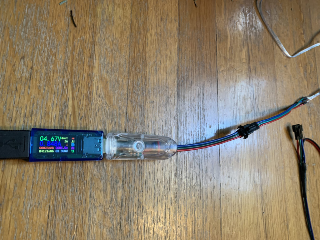
  • USB power meter for seeing voltage & amps drawn by any particular setup (see example below)
  • Arduino Pro Micro clone on tiny breadboard. This is a 5V microcontroller, so no need to worry about 3.3V -> 5V data issues. And it’s cheap in case we blow it up

Overall it’s working out okay. I need to add a few “sacrificial neopixels” to the mix to make using 3.3V-based microcontrollers and maybe some breadboard screw-terminals.

WS2812-compatible “fairy light” LEDs that know their address

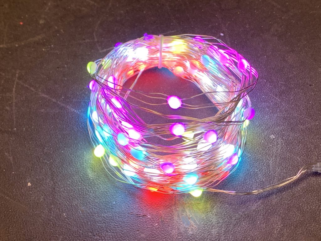
I’ve not done much on our plotter Xmas tree this week because, well… if you follow me on Twitter, it’s likely you’ve seen me ramble on about these crazy new Christmas Tree lights we got for our tree (first tree ever!). I wasn’t able to find appropriate “Christmas Tree” light forms of the WS2812 lights, but Carlyn did! And they were even better than normal Xmas light styles. These were “fairy lights” with small beads of light connected by solid enamel-coated wire that almost disappear visually. The LED string appeared to maybe be WS2812 / Neopixel compatible and yup, they were! But the weird thing was, as I learned was discovered back in November, these LEDs remember their address when cut out of the strand. If you’re familiar with WS2812-style LEDs, this is bonkers. Normally these LEDs have four pins: +5V, Gnd, DataIn, and DataOut. To make an LED strip, the LEDs are wired in a chain, one LED’s DataOut going to next LED’s DataIn. This is great! It means you just have one wire to control hundreds of LEDs!

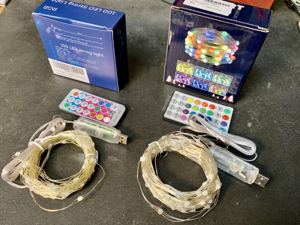
What’s going on with these LEDs? You cut them up, wire them in parallel (there’s no data “in” and “out”, just “data”) and they still know where they should be in the data stream, only picking the data for them. I’m still researching this with the help of some friends who can navigate Shenzhen better than me, but it’s looking like these LEDs have their address set OTP (one-time programmable) at the factory. No LED part number yet. If you’d like to get some to try yourself, here’s the 100-LED exact Amazon ASIN I bought as well as the 200-LED ASIN Carlyn originally found (both affil links).

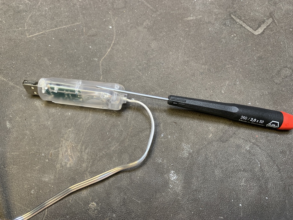
Here’s some pics showing the box and how I took it apart to test on an Arduino Micro clone.

Precise flood fill with AxiDraw

We recently got some inexpensive multicolored 0.3mm technical markers (AmzAffil) for use on the AxiDraw and they are pretty good! For this week’s batch of days for our 31-box AxiDraw calendar, I wanted to play with doing “flood fill” / solid color fills. Normally the “hatch fill” extension part of the AxiDraw Inkscape extensions creates slanted lines to imply a filled color. I knew a true full fill would be touchy because the paper can tear when fully inked, but I wanted to try. It turns out to work great!

There’s not much of a trick to it, just adjust the “hatch fill” algorithm to have closely-spaced lines (“2” for a 0.3mm pen worked well) and “connect nearby ends” to go back-n-forth to minimize pen up/down messiness. Also orienting your hatch direction, optimizing for your object (0º in my case) can make the fill succeed better. Plotting does take a while (especially for multi-colors like the 12 ornaments) and does cause some bleed-through. But I think it looks awesome.

And the video of it is mesmerizing:

Playing with AxiDraw for the Holidays

For the month of December, Carlyn and I are making a vaguely tree-shaped “calendar” with 31 boxes, 30mm x 30mm each. This is a design exercise to get us more familiar with the very fun EMSL AxiDraw, an easy-to-use pen plotter. We each get half of the days, randomly, and each of those days’ boxes must be filled with a little 30mm^2 bit of art. You can see the on-going progress on our Deep Fried Neurons Happy Hour posts and livestreams.

I’m not very experienced with pens and paper (when my 9th grade teach said I could turn my essays in on printout, my little dot matrix went into overdrive and I’ve never looked back). So messing around with pens and the AxiDraw (and just the aesthetics of plotters in general) has turned my eye towards 70s-era design. My “day 4” piece was the MICR check font I recall seeming so space-age when I saw it as a kid. Seeing the weird shapes of the MICR numbers without context makes them seem like alien symbology, which I guess they kind of are. For my “day 9” I went to 7-segment LED displays. I remember these displays being the epitome of high-tech with their otherworldly monochromatic red light. Now we’re so used to LED light it doesn’t seem strange. For my “day 6” I wanted to do something with hexagons (the bestagons). By now my design sense was firmly 40 years in the past. So I combined a very ’70s yellow-brown gradient (done with 4 marker types) and a six-unit pattern of hexagons. Hexagon grids was very space-age then, what with the hexagon-based space frames and geodesic domes.

By far the most difficult aspect of doing multicolor plots on the AxiDraw has been registering pens of different diameters. Carlyn came up with a clever trick of using transparency film to make re-zeroing easier, but I always am off a bit (see how the red of the “9” is a bit off) But one of the best aspects of the AxiDraw is the *tup* sound the pen makes as it drops to the surface. Listen to it in the video below.