Quickie Laser-cut iPhone/iPod Dock

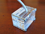
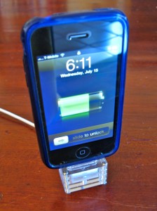
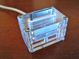
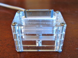
I recently got a case for my iPhone and it’s the kind that precludes the use of the dock. I kind of like the dock concept, but instead of taking a Dremel to the existing dock, I spent a few minutes drawing up a replacement that could be cut from acrylic scraps on the laser cutter. Here’s the result: (click for higher-res)
iphone-dock-1iphone-dock-1iphone-dock-1

iphone-dock-0

It is made of four slices of 1/4″ acrylic (actual width 0.22″). The top two slices have an oval opening just snug enough to fit the ipod connector and keep it in place with friction. The third slice has a channel for the cable to escape out the back, and the bottom slice keeps the cable from falling out and provides some pushback when the iphone is inserted. It’s held together by four 1″ 2-56 machine screws with nuts. I was a little concerned with the nuts scratching the table, so I’ve since added little hot glue feet to the bottom of each nut.

I didn’t add an additional layer at the top to provide lateral support of the iphone because I didn’t have long enough screws. And besides, it doesn’t seem to need it. If I get longer screws, I might make one that has the extra layer, which would also make the dock bigger, to encompass the bottom of the iPhone. And that would be good because it adds more mass to the dock, making it more stable.

If you want to try making one yourself, here are the files:
– iphone-dock.eps
– iphone-dock.svg
– iphone-dock.cdr

Also available on the wonderful Thingiverse

Laser Cut Laptop Stand (and o’scope hugger)

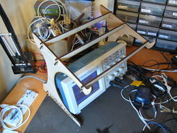
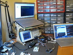
I have one of those USB-based logic analyzers that needs Windows software to make it go. I had been doing Windows-in-a-window with VMWare, but it’s kind of a pain. If I were to use a real Windows laptop, I’d need a shelf or something for it. I wanted it above my oscilloscope, which meant a laptop stand that was taller and wider than most. Time for the laser cutter!

todbot-laptop-stand-2todbot-laptop-stand-3
(click for larger)

My design requirements were:
– assemble without any tooling or fasteners
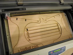
– fit on a single 1’x2′ sheet of the 1/4″ plywood I already had
– be stable enough to hold a 7lb laptop
– be wide & tall enough for the oscilloscope to fit underneath and be usable.

The 1/4″ (0.20″ really) plywood is cheap, from a big box hardware store. I think I paid $10 for a 4’x8′ sheet of it, and they nicely cut it down to 2’x4′ sheets for me.

It ended up fitting pretty exactly on the 12″x24″ cutting bed of the laser.
todbot-laptop-stand-1

If you want to make your own based off this, here are the vector files:
– todbot-laptop-stand-1.eps
– todbot-laptop-stand-1.pdf

What prodded me into doing this was the great Cardboard Laptop Stand I saw the oomlout guys had just received. Also, there are so many great DIY laptop stands on Instructables, they created a whole category for it.

Minimal Arduino with ATmega8

Or: A good use for old Arduino boards

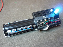
Like me, you may have a few old Arduino boards or ATmega8 chips (in the boards) laying around from when you were first playing with Arduino. Those chips can still be really useful as the heart of a tiny “Minimal Arduino” setup.

A normal Arduino board contains support components that make it easy to use. If you want a smaller footprint, you can get one of the many Arduino work-alike boards. But if you want a really small footprint, and reuse your old parts, you can make an Arduino board using just five components:
– ATmega8 chip
– single 10k resistor
– single 0.1uF capacitor
– tiny breadboard
– some hookup wire


(On the left, an IR remote controlled BlinkM. On the right an IR remote controlled RGB LED)
Continue reading “Minimal Arduino with ATmega8”

Arduino chip sticker label

I’ve been working with a super minimal Arduino setup recently. After seeing Alex’s awesome Arduino/ATmega breadboard header, where he notes there’s no room on the PCB for pin labeling, I wondered if it would be possible to make a small sticker that goes on the ATmega chip, labeling the pin names.

Here’s my first attempt:
arduino-atmega-sticker

And in use:
arduino-atmega-sticker-use

This was created by printing on a full-page sticker then laser cutting it to shape. I could have also just cut out the sticker with scissors, or used regular printer paper and double-sided tape.

Some files if you want to try this out yourself:
– arduino-atmega-sticker.eps — EPS of just the sticker itself.
– arduino-atmega-sticker.svg — SVG version
– arduino-atmega-sticker.pdf — PDF version
– arduino-atmega-sticker-lasercut.cdr — Coreldraw file containing instructions & registration marks for printing then laser cutting your own sticker.

Using MaxM with flexible RGB tape

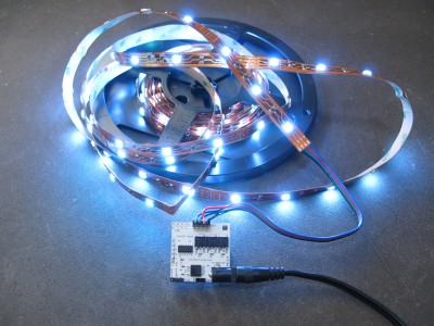
A single BlinkM MaxM can easily drive a 5 meter (16 ft) roll of the flexible RGB SMD LED tape that’s used for architectural lighting. Each roll contains 150 RGB LEDs.

maxm rgb led tape

Each LED in the tape is a SMD RGB "5050" LED, capable of putting out about 6000mcd. The spacing between LEDs is 3.3cm (~1.25").

Every 3 LEDs is a cut mark with solder tabs so you can cut or join pieces of tape.

Max current for a 5m roll is about 1.9 Amps. I did a quick test of MaxM driving three rolls at about 6A and it seemed fine.

This stuff is really cool. I’ve been buying it from this really great seller on ebay named "sunnytech".

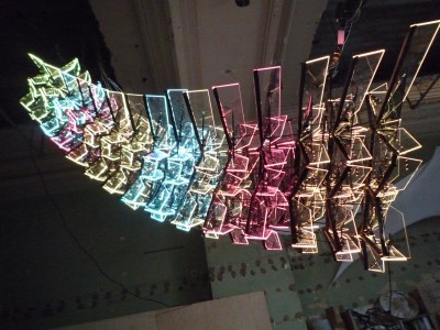
Here’s what you can do with it. Each of the 15 sections contains between 1 and 3 rolls of the tape.

crystal monster profile

Multiple BlinkM MaxM Blasters on one Master

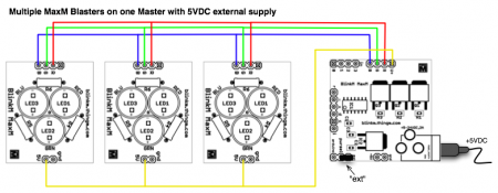
BlinkM MaxMs will be back in stock soon. Over on our GetSatisfaction area, there’s a question on how to use multiple BlinkM MaxM “Blaster” LED boards with one MaxM “Master” driver board. It’s possible and only just a little tricky. The Blaster board is powered by the 5V voltage regulator built-in to the Master board. That regulator is designed to power just one Master and one Blaster. If you try to drive multiple Blasters with it, it might work, but we don’t recommended it and could blow up your Master board.

Instead, it’s better to drive the MaxM with an external 5VDC power supply. This isn’t officially within the operating range of input voltage for the Master, but for this application it’s okay. To drive multiple Blasters, you then run that external 5VDC supply, available from the “V+” socket to the “5V” pin of each Blaster. And do not connect the Master’s “5V” to anything. Here’s a wiring diagram (click to enlarge):

maxm_multi_blasters

Continue reading “Multiple BlinkM MaxM Blasters on one Master”

Tiny Servos as Continuous Rotation Gearmotors

I’ve been exploring various types of gearmotors. DC motors by themselves spin too fast and have low torque. Gearmotors are motors with a gearbox that slows down the high speed of the motor and produces higher torque. Most gearmotors are pretty expensive though. I want a really cheap, almost throw-away, source of gearmotors. It turns out cheap servos can be made into continuous rotation gearmotors.

Modding servos for continuous rotation is not a new hack. You can find many examples of it. You can even buy a nice continuous servo made by Parallax. But I wanted a micro servo version. I’ve been getting cheap servo motors from Hobby City, and they have several super-tiny servos for less than $4. The ones I use here are the Hextronic HXT500 available for $3.49 each.

Here’s how to modify one of those servos to make it into a tiny little gearmotor.
Continue reading “Tiny Servos as Continuous Rotation Gearmotors”