I2CScanner: Arduino as I2C bus scanner

[2014-May-9: updated to work with Arduino 1.0 and moved into github]

One of the challenges of working with I2C (aka “two-wire” or “TWI” or “Wire”) devices is knowing the I2C address of the device. Older devices have a fixed address, or a “choose one-of-four” approach. But newer I2C devices have fully programmable addresses, leading to cases of not knowing what address a device is at.

Fortunately, there’s a technique one can use to “scan” an I2C bus and determine these addresses. Conceptually it’s very similar to a network “ping”. Below is an Arduino sketch “I2CScanner.pde” that turns an Arduino into an I2C bus scanner.

I2CScanner.ino — Turn Arduino into I2C bus scanner (github repo)

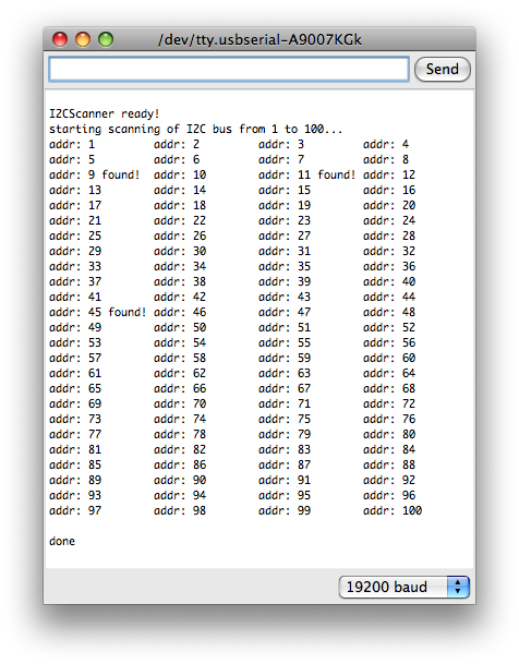
When loaded up on an Arduino, the sketch will immediately scan the I2C network, showing which addresses are responding.
i2cscanner-out

For example, the above output is from an I2C bus with four slave devices on it (one BlinkM MaxM, three regular BlinkMs).
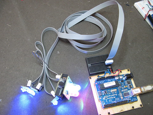
I2CScanner with BlinkMs
(Notice the 2 pull-up resistors on SDA & SCL. This is needed for longer bus lengths)

One thing to notice about the I2CScanner output is that although there are four devices on the bus, only three addresses were detected. This is because unlike IP networks and “ping”, you can’t tell if two devices have the same address. They’ll both respond to commands sent to them just fine, you just can’t read back data from them.

How it works

In I2C, the first byte transmitted/written by the master to a slave is the address of the slave. If there is a slave at that address, the slave will signal the I2C bus, otherwise it leaves it alone. We can use this to implement a bus scanner.

The Arduino “Wire” library utilizes a set of C functions called “twi.c”. One of those functions is “twi_writeTo()”. This function is used to both send the address of the slave down the bus and also to write data to slaves. It returns 0 if it was able to successfully transmit a byte or non-zero if it couldn’t. Since the very first write to a slave is its address, a very simple bus scanner using it would be:

void scanI2CBus(byte from_addr, byte to_addr) {
  byte data = 0; // not used, just a ptr to feed to twi_writeTo()
  for( byte addr = from_addr; addr < = to_addr; addr++ ) {
    byte rc = twi_writeTo(addr, &data, 0, 1, 0);
    if( rc == 0 ) {
      Serial.printl("device found at address "); 
      Serial.println(addr,DEC);
    }
  }
}

In the I2CScanner sketch, this function is extended a bit to support a callback function. The callback function is called with the result of every address scan. In I2CScanner, this callback function is called “scanFunc()” and just prints out “found!” or nothing, but it could be modified to do more complex tasks like doing additional I2C transactions to figure out what kind of device it is, or setting all the devices to a known state, etc.
Too Much RFID

[This post was part of a CrashSpace mailing list discussion on a “proximity t-shirt”: a shirt that would light up or similar when other similar t-shirts were nearby. People were wondering how good RFID was at localized detection of tags.]

Okay so I’m a big RFID nerd, did a lot of consulting work using it. So here’s a quick brain dump.

Regular passive RFID is designed for identification not localization. The RFID tags can be reliably read only to within a few centimeters. But the readers are cheap. You can get 128kHz (LF) and 13.56MHz (HF) RFID readers for $20-40 and the reader chips themselves for under $2. RFID tags that work with these systems are around $1. These systems typically cannot handle multiple tags in the reader’s field at a time.

UHF (900MHz-2.4GHz) passive RFID readers can read up to a few meters, and the tags can be a $0.05 in large quantities. The readers can get pretty expensive though: >$1000. These are the systems used by Walmart et al to read a palette of Mach3 razors as they transit the warehouse. And by the marathon race timers. The standard is called EPC, if you’re interested. These systems can handle a few hundred tags in the reader’s field, but read time goes down exponentially with tag count.

“Active RFID” has ranges up to hundreds of meters. The term “active RFID” is a bit loose, since one can describe a WiFi laptop or a cellphone as active RFID tag. Really it just means an RF radio system that transmits a unique ID using its own power source. There are active RFID versions of all the above technologies. Eric’s suggested use of the RF Link boards is essentially an active RFID beacon. One of my favorite active RFID designs is OpenBeacon (http://www.openbeacon.org/ ). It uses the ubiquitous Nordic RF chips (used in almost every wireless keyboard & mouse) Sparkfun has a ton of Nordic boards to play with.

“Localization” of RFID tags can mean two things. For normal passive RFID, the tag is “located” when a reader sees it. It’s a boolean: sees it / doesn’t see it. This is often called “proximity detecton”. So one way to approach localization is to just have a lot of readers. True localization (knowing where in a reader’s field-of-view a tag is) is pretty tricky. The main issue is just finding how far away an RF source is. The simplest is signal-strength (”the louder you are the closer you are”), but that falls prey to the non-homogeneity of the environment: in free space it would work; in a room full of RF-absorbing humans, it fails. If you’re really savvy, you can do time-of-flight calculation. The reader sends out a ping and measures the time it takes to receive the tag’s echo ping. This requires nanosecond-accurate clocks on the reader (speed of light is very fast) and falls prey to multipath distortion (reflections off the environment). And then you need multiple antennae for a single region to do triangulation. It’s hard, but RFID vendors are starting to release stuff.

Not a sunrise, but a galaxy rise

This is one of the greatest bits of youtubery I’ve ever seen, and I generally dislike auto-tuned stuff. Carl Sagan’s Cosmos was one of the most important things to happen to me as a child. This video & song gives me the shivvers. And makes me miss Sagan all the more.

I love the song’s chorus created from cut up Sagan quotes:

A still more glorious dawn awaits
Not a sunrise, but a galaxy rise
A morning filled with 400 billion suns
The rising of the milky way

(via jwz)

Behold the Crystal Monster

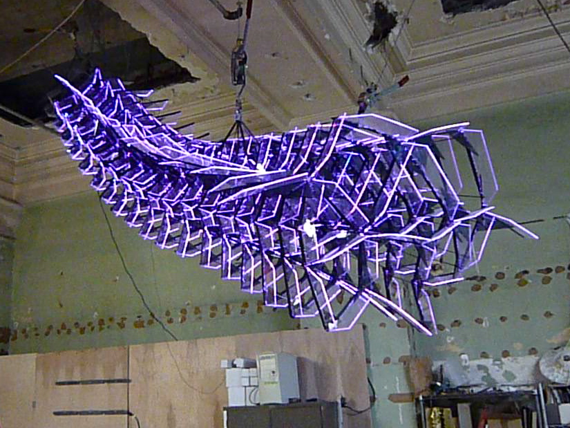
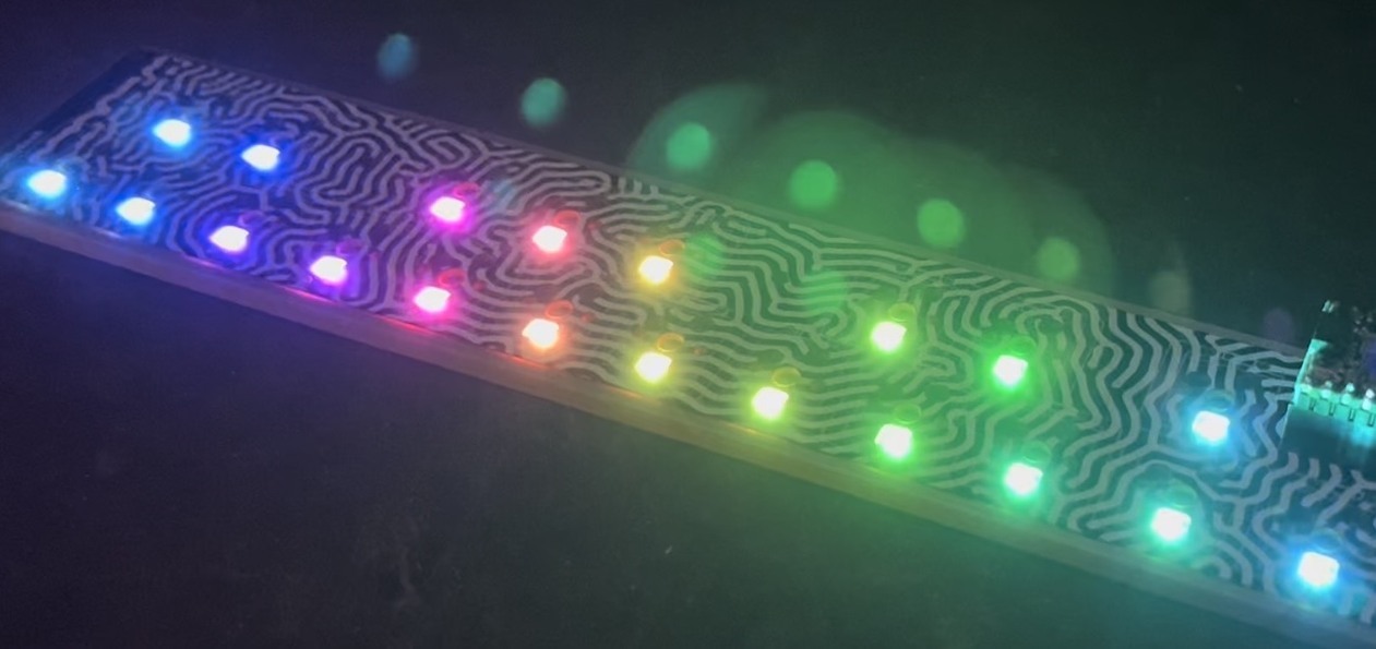
The Crystal Monster is an art piece created by Beverly Tang and Tod E. Kurt (me). It’s on display in the Continental Gallery on 4th & Spring St in downtown Los Angeles. The shape and structure of the Crystal Monster are Beverly’s design. I created the lighting and the electronics. It’s made from over 400 sheets of laser-cut acrylic, more that 240 feet of LED tape (>2200 RGB LEDs!), and around 500 steel rods and other steel hardware. It’s approximately 12 feet long and 10 feet wide and hovers 10 feet above your head. It’s got an Arduino brain and 18 BlinkM MaxMs (one per segment) to let it flutter color patterns up and down its length.

A little movie showing it in action:

Crystal Monster at Art Walk Downtown July 2009

Go to Beverly’s site for high-quality photos of the Crystal Monster. Check out her other work, she’s an amazing artist.

Some of my photos (or click to go to Flickr set):

crystal monster eating
crystal monster profile
Crystal Monster at Art Walk Downtown July 2009

It was first installed at the Ball-Nogues studio in Downtown Los Angeles as part of their participation in Downtown L.A. Art Walk, and lived there for a few months.
Crystal Monster: final assembly!

Then it moved to its mostly-permanent location at the Continental Gallery at 4th & Spring in Downtown Los Angeles.
Crystal Monster in its new home

It’s right on the corner, so you can really see it just from walking by on the street.

Crystal Monster from the street

The electronics consist of 18 BlinkM MaxMs driven by a single Arduino, all powered by an ATX power supply. The Arduino has an IR remote control receiver so the Monster’s behavior can be controlled from afar.

crystal monster control box

Arduino Serial protocol design patterns

[I posted this to the Arduino developer’s mailing list, but figured others might find it useful too]

When I first started with Arduino, I thought Serial.available() was a very loose wrapping of the RXC bit in the USCRA register, i.e. if I didn’t get data out of there fast, it’d be gone. That led to convoluted code like:

 if( Serial.available() ) {
   val1 = Serial.read();
   while( !Serial.available() );
   val2 = Serial.read();
   // and so on
 }

Yuck. So you end up designing protocols that are too terse. Or maybe you think you need to buffer so you don’t lose it:

 while( Serial.available() ) {
   commandbuffer[i++] = Serial.read();
 }

Then parsing becomes a two step process: read serial, parse buffer. Confusing to newbies perhaps, but at least it allows for a better protocol down the line. (And descend into madness as you gaze into the maw of strtok())

Because Serial contains these big comfy buffers, we often don’t need a second buffer to let us easily implement good protocols. My current favorite is to do something like this:

 // protocol is "CCaaaa", two bytes of command, four bytes of args
 if( Serial.available() >= 6 ) {  // command length is 6 bytes
   cmd0 = Serial.read();
   cmd1 = Serial.read();
   arg0 = Serial.read();
   arg1 = Serial.read();
  // ...etc...
 }

I don’t think I’ve seen any Serial examples that check for a specific number of bytes available. It’s really handy.

Implementing a human-friendly protocol like “command arg0 arg1 arg2”, where command and args are space-separated strings like “servo 12 0xff”, is currently hard with Serial. I do this right now with a 2nd buffer and lots of C hackery:

 char* cmdbuf; char c; int i;
 while( Serial.available() && c!= '\n' ) {  // buffer up a line
   c = Serial.read();
   cmdbuf[i++] = c;
 }

 int i = 0;
 while( cmdbuf[++i] != ' ' ) ; // find first space
 cmdbuf[i] = 0;          // null terminate command
 char* cmd = cmdbuf;     //
 int cmdlen = i;         // length of cmd

 int args[5], a;         // five args max, 'a' is arg counter
 char* s; char* argbuf = cmdbuf+cmdlen+1;
 while( (s = strtok(argbuf, " ")) != NULL && a < 5 ) {
   argbuf = NULL;
   args[a++] = (byte)strtol(s,NULL,0); // parse hex or decimal arg
 }
 int argcnt = a;         // number of args read

This sort of functionality would be great in a library I think. Maybe not in Serial, but a core class.

Any other protocols people like to use and the Arduino code they use to do it?

Quickie Laser-cut iPhone/iPod Dock

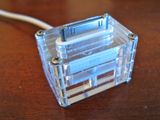
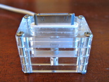
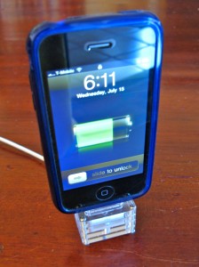
I recently got a case for my iPhone and it’s the kind that precludes the use of the dock. I kind of like the dock concept, but instead of taking a Dremel to the existing dock, I spent a few minutes drawing up a replacement that could be cut from acrylic scraps on the laser cutter. Here’s the result: (click for higher-res)

iphone-dock-1iphone-dock-1iphone-dock-1

iphone-dock-0

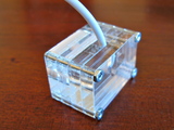
It is made of four slices of 1/4″ acrylic (actual width 0.22″). The top two slices have an oval opening just snug enough to fit the ipod connector and keep it in place with friction. The third slice has a channel for the cable to escape out the back, and the bottom slice keeps the cable from falling out and provides some pushback when the iphone is inserted. It’s held together by four 1″ 2-56 machine screws with nuts. I was a little concerned with the nuts scratching the table, so I’ve since added little hot glue feet to the bottom of each nut.

I didn’t add an additional layer at the top to provide lateral support of the iphone because I didn’t have long enough screws. And besides, it doesn’t seem to need it. If I get longer screws, I might make one that has the extra layer, which would also make the dock bigger, to encompass the bottom of the iPhone. And that would be good because it adds more mass to the dock, making it more stable.

If you want to try making one yourself, here are the files:

iphone-dock.eps
iphone-dock.svg
iphone-dock.cdr

Also available on the wonderful Thingiverse