Or: A good use for old Arduino boards
Like me, you may have a few old Arduino boards or ATmega8 chips (in the boards) laying around from when you were first playing with Arduino. Those chips can still be really useful as the heart of a tiny “Minimal Arduino” setup.
A normal Arduino board contains support components that make it easy to use. If you want a smaller footprint, you can get one of the many Arduino work-alike boards. But if you want a really small footprint, and reuse your old parts, you can make an Arduino board using just five components:
– ATmega8 chip
– single 10k resistor
– single 0.1uF capacitor
– tiny breadboard
– some hookup wire


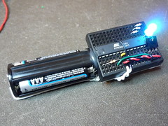
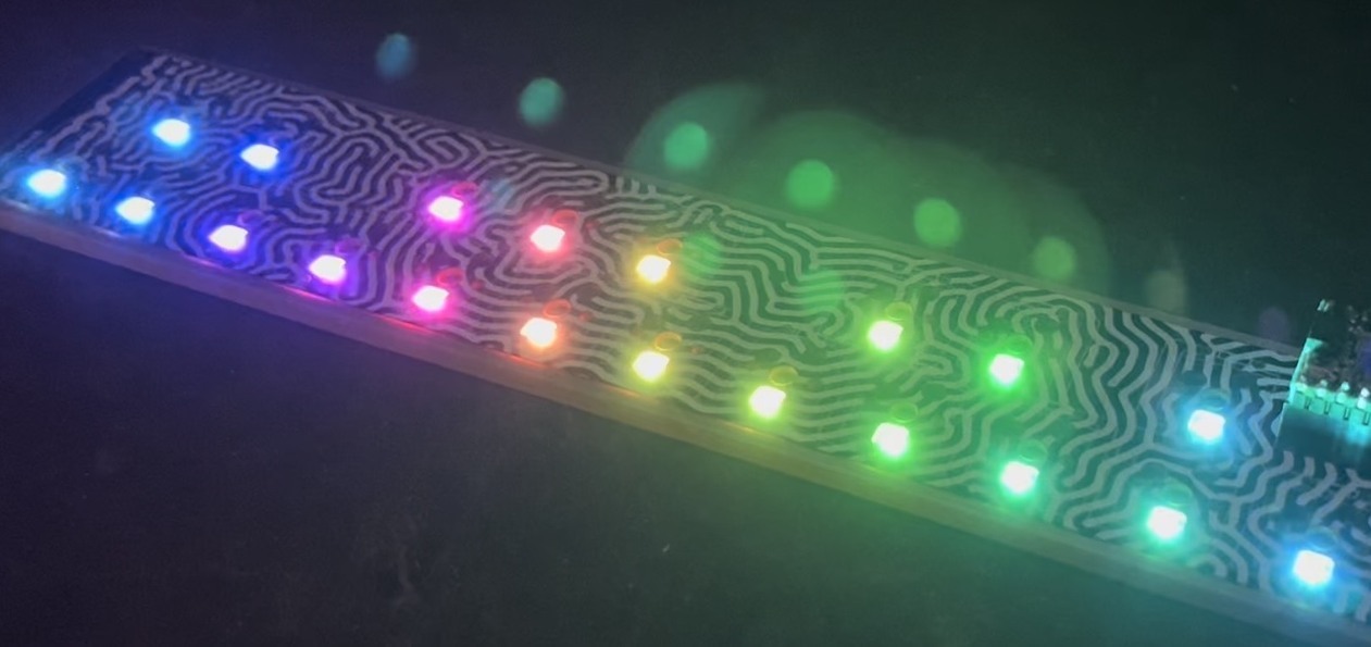
(On the left, an IR remote controlled BlinkM. On the right an IR remote controlled RGB LED)
The Circuit
The minimal Arduino circuit is dead simple. It relies on the internal 8MHz oscillator (like the Lilypad Arduino). And like the Lilypad, it doesn’t include a USB-to-serial. You have to provide that with a FTDI USB-to-serial cable or with an old Arduino board.

Eagle-format minimal-arduino.sch file
Getting the Arduino bootloader into the ATmega8
While the circuit is very similar to a Lilypad Arduino, the chip used is different. The ATmega8 has less memory and must be programmed slightly differently than the Lilypad’s ATmega168.
So a modified Arduino bootloader needs to be programmed into the ATmega8. The bootloader is a small program on the chip that listens to the serial port on power up and can reprogram the rest of the chip if instructed to. Here, a variant of the standard “Arduino NG” bootloader is used. The modifications are:
– uses internal 8MHz oscillator (no external part required)
– serial speed is 38400 instead of 19200 for faster uploads
Files for Minimal Arduino ATmega8 bootloader:
– atmega8_noxtal.zip
Unzip this file into the “arduino-0015/hardware/bootloaders” directory of your Arduino installation to create the directory “atmega8_noxtal”. The zip file contains:
– ATmegaBOOT.hex — the actual bootloader to program
– ATmegaBoot.c — the source code of the bootloader
– Makefile — Makefile to produce & program the bootloader
Actually programming the bootloader to the ATmega8 chip can be done in a few ways. I prefer using an AVRISPmkII programmer and an old Arduino board. Seat the ATmega8 into the Arduino, plug the AVRISP into the 6-pin “ICSP” header, plug both into USB, and program the ATmegaBOOT.hex file. If you are familiar with the command-line, go into the “atmega8_noxtal” directory and type “make isp” to program. If not, you can have the Arduino software program it for you once you tell it about this new kind of Arduino board.
Configuring Arduino to use Minimal Arduino
Because this minimal Arduino setup isn’t exactly like any other previous Arduino boards, we need to tell the Arduino software how to talk to it. In the Arduino directory, there is a file called “arduino-0015/hardware/boards.txt” that does this. Open that file in a text editor and add these lines to it:
##############################################################

atmega8noxtal.name=ATmega8-noxtal @8MHz

atmega8noxtal.upload.protocol=stk500
atmega8noxtal.upload.maximum_size=7168
atmega8noxtal.upload.speed=38400

atmega8noxtal.bootloader.low_fuses=0xe4
atmega8noxtal.bootloader.high_fuses=0xc4
atmega8noxtal.bootloader.path=atmega8_noxtal
atmega8noxtal.bootloader.file=ATmegaBOOT.hex
atmega8noxtal.bootloader.unlock_bits=0x3F
atmega8noxtal.bootloader.lock_bits=0x0F

atmega8noxtal.build.mcu=atmega8
atmega8noxtal.build.f_cpu=8000000L
atmega8noxtal.build.core=arduino
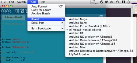
The next time you start up the Arduino software, you should have a new entry of “ATmega8-noxtal @8MHz” in the “Boards” menu. It will look something like this:
From this point you could burn the bootloader onto the ATmega8 chip by going to the “Burn Bootloader” menu and selecting “w/ AVRISP mkII”.
Uploading Arduino sketches
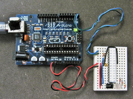
Once the bootloader has been installed, you can leave it plugged into the Arduino board to test it out, or you can remove it and place it on your minimal Arduino breadboard. To upload sketches to it, the easiest way I’ve found is to run a few wires from an old Arduino board to the breadboard:
Links / Resources
This minimal Arduino idea is nothing new. Many others have done similar things. If I could have found an Arduino clone that used an internal 8MHz oscillator on ATmega8, I would’ve used it instead. Some of the pages I referenced:
– Bootloader page on Arduino.cc
– Setting up Arduino on a Breadboard from Tom Igoe at ITP
– Standalone Arduino on the Arduino Playground
– Boarduino from Adafruit
– Really Bare Bones Board Arduino-compatible board from Modern Device
– Arduino Core Hardware page on the Arduino Playground


the avrdude message is:
avrdude: stk500_getsync(): not in sync: resp=0x00
avrdude: stk500_disable(): protocol error, expect=0x14, resp=0x51
I’ve selected the noXtal 8Mhz version in the IDE.
thanks for looking into this !
Also, here’s a really great tool for figuring out AVR fuse values:
http://www.engbedded.com/fusecalc/
Hi Jan,
If you’re using the firmware I link to above, you’ll need to upload the sketch within a few seconds of powering on the breadboard (or you could press reset if you have one wired up)
Other than that, it sounds like you might have the wrong board type selected in the Arduino IDE. What’s the exact avrdude message you see?
Hi, I tried this with an ATMega8 as well, but I can’t upload any sketches, not on a breadboard, nor on a duemilanove. LED is blinking slowly and I get the odd avrdude error message.
I have an AVRISPMKII and a Duemilanove board with an AtMega168. I am trying to apply this to an ATMega168, running 8MHz, no external clock, but have some difficulties understanding this:
– how do I calculate the fuses? Where do I get the “original values” from?
– do I still use one of the existing bootloaders (e.g. atmega168, 8Mhz), because all Arduino boards seem to have a resonator/crystal, even on 8 mhz
– can I still run it on 5V or does 8 Mhz imply the reduction to 3.3V as well?
MANY Thanks for enlightening me
Jan
Atmel’s document ‘AVR042: AVR Hardware Design Considerations’ says that the short bursts of current that the AVR MCU uses is, or should, be supplied from a small capacitor placed close to the Vcc and GND pins on the chip.
For me, new to this and trying to learn, documents like this are very valuable, as is of course this discussion with you.
Yup, that’s exactly what I use my breadboarded version for: Arduino-like experiments where I’m afraid I might fry the Arduino. :)
And the various conceptions of what the capacitor does (filter AC noise or act as charge reserve) are actually two ways of looking at the same thing. I often think of a capacitor as a little “bucket” of charge with a leaky hole in it. If the current pouring into it like an old hose, varying but sorta constant (e.g. a mostly constant DC voltage with a small AC signal on top), then the charge bucket will stay mostly full and leak out at a constant rate. The rate of the leaking will not depend on the small variation from the hose. If the variation becomes too great (more AC than DC), the bucket will empty, as you’d expect. Or if the leaky hole is too big (current draw too high), the bucket will also empty, and you lose your charge reserve. This metaphor breaks down if you start getting more detailed than that, but it works for a lot of capacitor cases.
Of course, silly me. A pullup resistor should go to Vcc, not GND. I am at work now, the protoboard is at home, but looking at the second photo I would say that it looks like I did actually build it right, but the schematics I published puts the resistor between RST and GND, completely wrong.
Stupid mistake, but being primarily a “computer guy” the actual wiring and electronics are still a bit esoteric to me. I know that there should be a capacitor between Vcc and GND, and I thought that it was not primarily for storing current, more for filtering out any “AC” noise, but reading some app note from Atmel just a few days ago tought me that it actually is supposed to be a power reserve too. What I am trying to say is that this electronics side of things is new to me, I am trying to get a better understanding of the theory, but right now I am more at the “connect the dots” stage than actually creating a work of art on my own.
Yes, I could add headers and stuff, but building this little thing was more for fun, and for having an easier way of connecting a chip to the ISP for programming, and then testing it. It still feels kind of wrong to tear the brains out of my sweet little Arduino, installing a mindless brain template and let the power of lightning burn a mind of my choosing into it. Or maybe I am afraid of damaging either the Arduino hardware itself or the original chip. I will use it as a simple testing platform.
The 10k resistor should go between RESET and Vcc, not Gnd. (there is an internal pullup inside the AVR, which I think is why the chip isn’t being constantly held in reset)
The protoboard version looks great! You could solder some header sockets onto the side to make it easy to plug stuff into (or downward-facing headers to make it pluggable into a breadboard)
All of the above, I’d say. 10k resistor from GND to RST, all GND pins connected to each other, Vcc connected to AVcc with 100n capacitor to GND, Aref floating. Power from SparkFun FTDI Basic (FTDI 232R something, USB powered), works for my Pro Mini. Pictures and schematics on my blog now.
Hi Johan,
Congrats, I can’t wait to see your setup, it sounds great.
I’ve used AVRs with internal oscillators a lot. I wouldn’t expect that to be the problem. I _have_ had issues with AVRs being flaky if not all the Vcc & Gnd pins are connected, if 0.1uF bypass capacitors between Vcc & Gnd are missing or aren’t placed close enough to the chip, or if the power supply is noisy.
Your fuse settings look good. Basically copying Lilypad is what I would do too. :) Do you have the 10k pullup resistor on RESET? If you use the DTC 0.1uF capacitor trick, I think adding the resistor will make it work more consistently.
I built one on protoboard now, with FTDI port and ISP port, LED connected as on Arduino, and working auto reset on program upload. Well, it works some times, not other. My guess is that it has to do with the internal oscillator not being stable enough, since avrdude through the AVRISP MkII has the same sporadic success.
I will post schematics (Eagle even designed a nice PCB), photos and all later, on my English blog. It feels kind of cool, I added a capacitor, a LED, a bit more wire and a piece of protoboard, and I am close to a working (though extremely simple) Arduino clone. I have been playing with electronics and MCU:s for a few weeks, so it’s a big moment for me. :-)
Thank you for the inspiration!
It works fine with a 328P, took me less than 10 minutes to get one running. :-)
The fuses are (l/h/e) 0xe2 0xda 0xe5. I used the fuse calculator at http://www.engbedded.com/fusecalc/, entered original fuses in bottom end, changed to internal osc 8 MHz (default value) at top, and it gave me this (which works).
In boards.txt I cloned the Lilypad 328 entry, changed its name, kept the bootloader, changed the fuses (really just the low fuses). The full entry now looks like this:
——–
# Johan Adler, from TodBot http://todbot.com/blog/2009/05/26/minimal-arduino-with-atmega8/#more-494
atm328int8.name=ATmega328 internal oscillator 8 MHz
atm328int8.upload.protocol=stk500
atm328int8.upload.maximum_size=30720
atm328int8.upload.speed=57600
atm328int8.bootloader.low_fuses=0xE2
atm328int8.bootloader.high_fuses=0xDA
atm328int8.bootloader.extended_fuses=0x05
atm328int8.bootloader.path=atmega
atm328int8.bootloader.file=ATmegaBOOT_168_atmega328_pro_8MHz.hex
atm328int8.bootloader.unlock_bits=0x3F
atm328int8.bootloader.lock_bits=0x0F
atm328int8.build.mcu=atmega328p
atm328int8.build.f_cpu=8000000L
atm328int8.build.core=arduino
——–
I thought that adding a 100 nF capacitor between reset and the DTR/RTS line on an FTDI cable or DTR-wired adapter would even give it auto-reset capability, but it did not work the first time I tried it. Would have been a nice touch, though.
Hi Gary,
You need to program the Arduino bootloader into the ATmega328 before it will work in the Arduino board. Adafruit.com sells preprogrammed ones, or you can get an AVR programmer and program them yourself.
Once you have an Arduino-compatible ATmega, then you can load a sketch onto it with the Arduino application. To pop the chip out and use it on a motherboard, see the “Setting up Arduino on a Breadboard” and “Standalone Arduino” links above.
Hi Todd,
I’m new to Arduino and have found your site really helpful. I some really simple projects in mind but don’t want to use my Arduino permanently in them. If I buy an Atmega328, program it in my current Arduino, then pop it out and set it up in a bread board, would that work too?
Thanks!
Gary
Hi Bill,
Yes, I’m pretty sure it should, but have not tried it yet. This was mostly an experiment for me to find a use for the ~30 ATmega8s I have laying around. :)
This is great – does the same circuit work for an atmega168 and, if so, can I just use the lilypad definitions and bootloader?