Or: A good use for old Arduino boards
Like me, you may have a few old Arduino boards or ATmega8 chips (in the boards) laying around from when you were first playing with Arduino. Those chips can still be really useful as the heart of a tiny “Minimal Arduino” setup.
A normal Arduino board contains support components that make it easy to use. If you want a smaller footprint, you can get one of the many Arduino work-alike boards. But if you want a really small footprint, and reuse your old parts, you can make an Arduino board using just five components:
– ATmega8 chip
– single 10k resistor
– single 0.1uF capacitor
– tiny breadboard
– some hookup wire


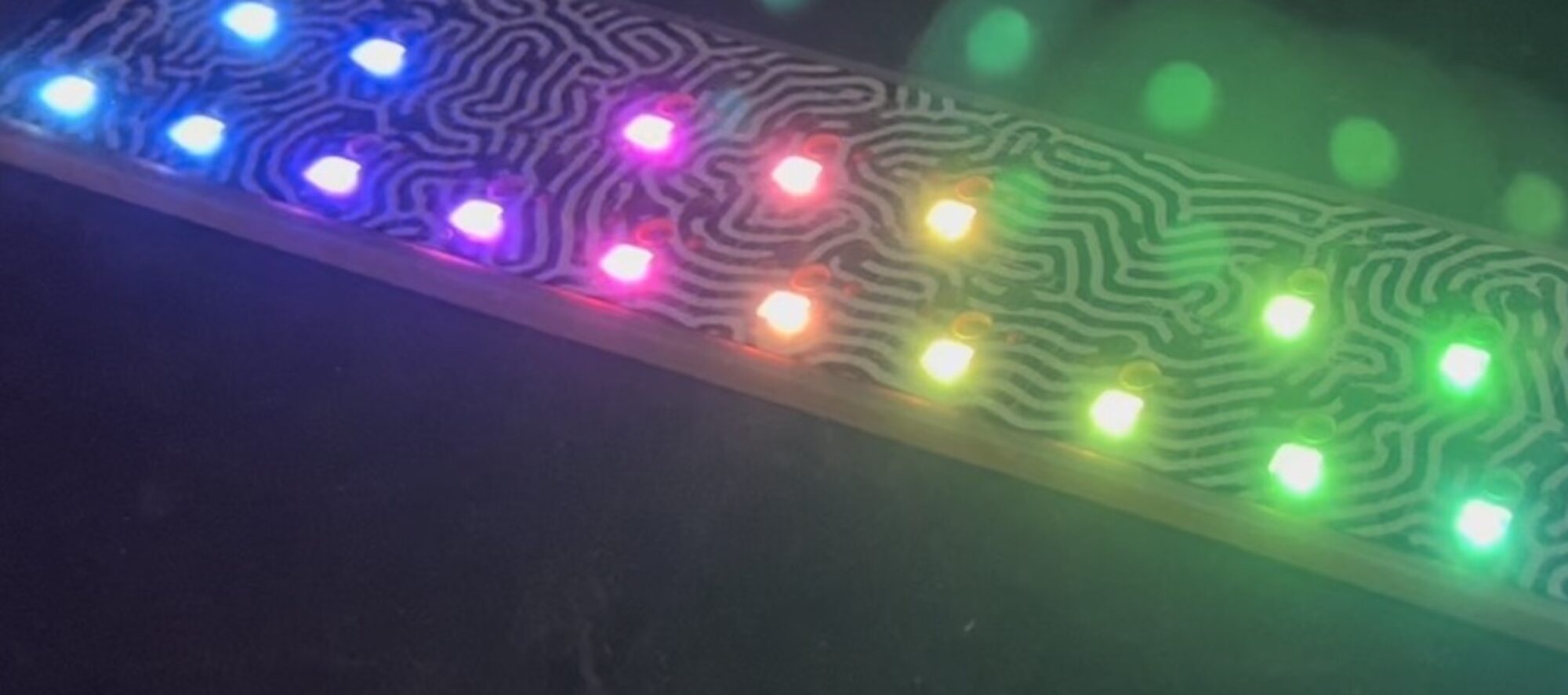
(On the left, an IR remote controlled BlinkM. On the right an IR remote controlled RGB LED)
The Circuit
The minimal Arduino circuit is dead simple. It relies on the internal 8MHz oscillator (like the Lilypad Arduino). And like the Lilypad, it doesn’t include a USB-to-serial. You have to provide that with a FTDI USB-to-serial cable or with an old Arduino board.

Eagle-format minimal-arduino.sch file
Getting the Arduino bootloader into the ATmega8
While the circuit is very similar to a Lilypad Arduino, the chip used is different. The ATmega8 has less memory and must be programmed slightly differently than the Lilypad’s ATmega168.
So a modified Arduino bootloader needs to be programmed into the ATmega8. The bootloader is a small program on the chip that listens to the serial port on power up and can reprogram the rest of the chip if instructed to. Here, a variant of the standard “Arduino NG” bootloader is used. The modifications are:
– uses internal 8MHz oscillator (no external part required)
– serial speed is 38400 instead of 19200 for faster uploads
Files for Minimal Arduino ATmega8 bootloader:
– atmega8_noxtal.zip
Unzip this file into the “arduino-0015/hardware/bootloaders” directory of your Arduino installation to create the directory “atmega8_noxtal”. The zip file contains:
– ATmegaBOOT.hex — the actual bootloader to program
– ATmegaBoot.c — the source code of the bootloader
– Makefile — Makefile to produce & program the bootloader
Actually programming the bootloader to the ATmega8 chip can be done in a few ways. I prefer using an AVRISPmkII programmer and an old Arduino board. Seat the ATmega8 into the Arduino, plug the AVRISP into the 6-pin “ICSP” header, plug both into USB, and program the ATmegaBOOT.hex file. If you are familiar with the command-line, go into the “atmega8_noxtal” directory and type “make isp” to program. If not, you can have the Arduino software program it for you once you tell it about this new kind of Arduino board.

Configuring Arduino to use Minimal Arduino
Because this minimal Arduino setup isn’t exactly like any other previous Arduino boards, we need to tell the Arduino software how to talk to it. In the Arduino directory, there is a file called “arduino-0015/hardware/boards.txt” that does this. Open that file in a text editor and add these lines to it:
##############################################################

atmega8noxtal.name=ATmega8-noxtal @8MHz

atmega8noxtal.upload.protocol=stk500
atmega8noxtal.upload.maximum_size=7168
atmega8noxtal.upload.speed=38400

atmega8noxtal.bootloader.low_fuses=0xe4
atmega8noxtal.bootloader.high_fuses=0xc4
atmega8noxtal.bootloader.path=atmega8_noxtal
atmega8noxtal.bootloader.file=ATmegaBOOT.hex
atmega8noxtal.bootloader.unlock_bits=0x3F
atmega8noxtal.bootloader.lock_bits=0x0F

atmega8noxtal.build.mcu=atmega8
atmega8noxtal.build.f_cpu=8000000L
atmega8noxtal.build.core=arduino
The next time you start up the Arduino software, you should have a new entry of “ATmega8-noxtal @8MHz” in the “Boards” menu. It will look something like this:

From this point you could burn the bootloader onto the ATmega8 chip by going to the “Burn Bootloader” menu and selecting “w/ AVRISP mkII”.

Uploading Arduino sketches
Once the bootloader has been installed, you can leave it plugged into the Arduino board to test it out, or you can remove it and place it on your minimal Arduino breadboard. To upload sketches to it, the easiest way I’ve found is to run a few wires from an old Arduino board to the breadboard:

Links / Resources
This minimal Arduino idea is nothing new. Many others have done similar things. If I could have found an Arduino clone that used an internal 8MHz oscillator on ATmega8, I would’ve used it instead. Some of the pages I referenced:
– Bootloader page on Arduino.cc
– Setting up Arduino on a Breadboard from Tom Igoe at ITP
– Standalone Arduino on the Arduino Playground
– Boarduino from Adafruit
– Really Bare Bones Board Arduino-compatible board from Modern Device
– Arduino Core Hardware page on the Arduino Playground
Actually, I manged to compile it with some simple modifications of above boards.txt entry
I changed bootloader.file path and aded build.board and build.variant entries. It compiles successfully and I flashed resulting hex via USBASP directly to Atmega8 and it works fine and without external oscillator.
Hi, this is a pretty old article and the exact settings probably don’t work any more. Instead, I would use the “Lilypad Arduino” board setting that comes with the Arduino IDE. The Lilypad Arduino is basically an ATmega328 minimal Arduino.
The programming of the bootloader is basically the same: Select “Lilypad Arduino” from the Board menu, select your programmer type (I use “AVRISP mkII”), and then select “Burn Bootloader”.
To upload your sketch, keep the Board selected to be “Lilypad Arduino” and do “Upload” as normal.
I was able to install the boot loader without an error message. But when I tried to upload some code, I got “programmer not responding”. With the same circuit uploading code to a stand-alone atmega328 with a different boot loader was not a problem, so my circuit should be fine. Any suggestions?
For IDE 1.0.5 you must add the follow line in boards.txt:
atmega8noxtal.build.variant=standard
(after your lines)
without you will get a error message
Do you have a compiled version with 1Mhz internal clock ?
Hi,
After all I think I do find what was wrong.
In the file boards.txt the line:
atmega8noxtal.bootloader.high_fuses=0xc4
has to be
atmega8noxtal.bootloader.high_fuses=0xca
This is because of the bootloader size, if you look at the hex file, it begans @ 0x1C00 (in byte) so 0xE00 (in word). If you look in the datasheet for this it’s BOOTSZ0=1, and BOOTSZ1=0 that leads to the correct hfuses value (this is confirmed if you have a look in the makefile).
I’m going to deep test this but it seems that all my problems above are solved.
Again thanks for this page.
Nice thing,
I had success with the comments of Pope and Darko.
First of all, I’am using ATMEGA8-16PU.
I notice a little thing annoying :
When I use a freshly flashed atmega with the bootloader, I can upload only one time easily from arduino rad.
After the sketch is uploaded on the atmega8 and when I reset to upload an other one, it’s hard to get the bootloader responding.
Here are my observations :
– After a fresh flash of the boolloader, there is nothing on the atmega and it seems that the bootloader is cycling forever, waiting for an upload (because you can see the led on PB5 strobe every 3 or 4 seconds)..
– Just after a reset the led on the PB5 is not flashing, but is staying OFF for 4 seconds, I think it’s the first cycle of the bootloader and during this cycle the bootloader is not responding, all the subsequent cycle works (led strobing and bootloader answering).
=> So if there is no program on the atmega the bootloader is cycling and from the second cycle it responds and it’s all OK.
=> If there’s a program on the atmega the bootloader isn’t cycling forever (only one or two times I think) and if you don’t have a led on the PB5 it’s hard to know when to click on upload because during the first cycle bootloader doesn’t respond. So it’s quite tricky : first reset, then wait (approx 4 seconds) for the led on PB5 to strobe, then click upload.
I hope this will help other-ones stuck in the same problem !
Hi, great notes.
Nevertheless, regarding the skagus comment on avrdude and using arduino 1.0.5 (with included avrdude 5.11) I also had to change the upload protocol (in boards.txt) to be able to use:
1. the auto reset function
2. proper signature check
Change:
atmega8noxtal.upload.protocol=stk500
To:
atmega8noxtal.upload.protocol=arduino
Now upload works fine with ATMega8L.
With protocol=stk500 I had to use manual upload copying the arduino upload command to cmd window and adding ‘-F’ option.
But I do find auto reset to be a little late – if reset is connected to the ’empty’ Uno board.
Because of this issues with auto reset I am rather using your boards.txt settings and Arduino Uno as ISP to upload the programs to the ATMega 8L without using the bootloader.
Thanks for this fix!
However, using 1.0.5, we get a compilation error, so we need to add the line
atmega8noxtal.build.variant=standard
to your modification of “boards.txt”.
As I work with DIY arduino, I have the scenario as Saburo,
And I have clue with this problem.
No-xtal arduino has the bootloader and it is same with original atmega8 arduino boot loader(except baud rate of serial port). It means the bootloader has no problem. The problem is avrdude.
avrdude support AVR ISP protocol. The protocol has 2 ways to get signature bytes. 1st is via ‘u’ command in the protocol. It is only for getting signature. And 2nd way is using ‘V’ command. It is for general use of ISP.
I can’t know why avrdude use ‘V’ command for signature. But, as it use the ‘V’ command, the bootloader can’t give correct response.
(‘V’ command is too hard to code in bootloader)
I have the exact scenario as Saburo,
Hello, I am trying to load the bootloader on an atmega8-16pu, but I keep getting a “wrong signature” message.
I am using an arduino uno as ISP with pins 10,11,12,13 respectively rest,mosi, miso, sck.
I have a 22uF capacitor on the arduino board hooked between gnd and reset pins.
I keep getting a “invalid signature”, tried with protocol = arduino and with protocol = stk500. with high fuse = c4 (if I chzange it to c2 I get another message,
like it’s not communicating with the target).
Does the provided atmega8_noxtal loader work with the atmega8-16pu?
Did you ever figure this out?
Hello, I am trying to load the bootloader on an atmega8-16pu, but I keep getting a “wrong signature” message.
I am using an arduino uno as ISP with pins 10,11,12,13 respectively rest,mosi, miso, sck.
I have a 22uF capacitor on the arduino board hooked between gnd and reset pins.
I keep getting a “invalid signature”, tried with protocol = arduino and with protocol = stk500. with high fuse = c4 (if I chzange it to c2 I get another message, like it’s not communicating with the target).
Does the provided atmega8_noxtal loader work with the atmega8-16pu?
Hi,
I just ordered a atmega168A-PU chip from protostack. Can I use the same setup as you have shown for this chip. I want to stick to the factory default clock settings. Should I be able to do this.
Thank you for any advise …
VR