Spooky Arduino Projects #4 – Musical Arduino

spooky arduino projectsarduino class merit badge

The notes for the fourth and final class are up on the Spooky Arduino class page. At the end of the class, Mark of Machine Project bestowed upon each of the students a merit badge. It was great. Click above for a larger view of the badge.

Arduino MIDI Drum Kit and Spooky Sound Trigger

Here’s a quick project using techniques from this week’s class that turns an Arduino board and a few buttons and piezos into a MIDI drum kit or scary sound trigger. Hide piezo sensors around the house during your Halloween party to trigger scary sounds when people walk around!

Hardware

The hardware is an Arduino board with a MIDI jack, a few buttons, and two piezos attached to it. It runs off of a 9V battery.

arduino midi schematic

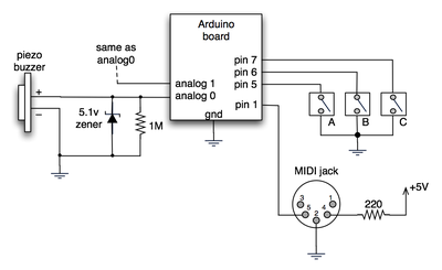
(Note: depending on what kind of MIDI connector you’re usign (jack or cut-off cable), you may need to swap the connections to MIDI pins 4 & 5).

For the piezo input, the 1M resistor is to bleed off the voltage generated by the piezo when it is struck. The 5.1v zener diode is there to insure any large voltages don’t make it into the Arduino and blow it out.

Arduino code

The code has a few tricks that may not be immediately obvious. First is that to implement a MIDI interface, all you really need is the ability to send serial data at 31,250 bps. This is easily done with “Serial.begin(31250)“. Once that is done, a complete three-byte MIDI note-on message can be sent with three “Serial.print(val,BYTE)” commands.

The next tricky bit is that the switches in the above schematic don’t need pull-up resistors. This is because the internal pull-ups in Arduino’s AVR chip are turned on with a “digitalWrite(pin,HIGH)“. This may seem counter-intuitive, doing a digitalWrite() on an input pin, but it’s how the AVR works. The benefit is that you no longer need a resistor to +5V and the effort to wire up each additional button is much lower.

The final trick is measuring impact force on a piezo. When piezo elements are struck, their output voltage rings, sort of like a bell. Kind of like this:
piezo whack!

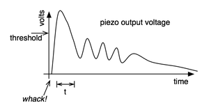
By measuring the time it takes for that first big jolt to cross a threshold, you can get an idea as how big the force was. In the code this is represented by reading the analog value and if it’s over the threshold, wait until it drops down again, counting all the while. When I’ve done this before, I used an input opamp to convert the analog signal to digital (thus doing thresholding in the analog domain) and then used interrupts to get very accurate force measurements.

Arduino code: midi_drum_kit

References

DIY Ambient Orb with Arduino, update

There’s been some confusion as to whether or not the DIY RGB orb presented in the last post was actually connected to a computer and receving color data from it. Here’s a video that more accurately depicts what’s going on and all the code used to create it.

Hardware

The hardware is just an Arduino board connected via USB to a laptop. The Arduino appears as a serial device to the computer. On the Arduino board, three LEDs (red,green,blue) are mounted directly to the Arduino board using a prototyping shield like this DIY one. The schematic is quite simple:
rgb_led_schematic.png

Arduino code

The code sketch running on the Arduino board is a slightly modified version of the one presented in the last Spooky Arduino class. Instead of parsing single color values over the serial port, it expects a full RGB color value in standard web format of “#RRGGBB” (white is “#ffffff”, blue is “#0000ff”, and so on). The sketch parses that seven character string into three bytes: one each for the brightness values of the red, green and blue LEDs.

Arduino code: serial_rgb_led_too.pde

Processing code

To bridge between the Arduino and the Net, a small Processing sketch was created that uses the standard Java HTTPURLConnection class to fetch a web page (really, a text file on a web server) containing a line with a color value in the format “#RRGGBB”. The sketch parses the color value, sends the value out to the Arduino orb using the Processing Serial library, and then sets its own background color to match. Because I’ve set the framerate of the sketch to 1 fps, it takes a second for the background to match the orb. I did this on purpose so I could get a sense of the color as the orb reproduces it before seeing it as it truly is. I was surprised how well the two tended to match!

Processing code: http_rgb_led.pde

Better Video on OS X: NicePlayer & Perian

nice and happy

I watch movies on my Mac. I’ve been ripping my DVDs to DivX or h.264 to my hard drive simply because it’s easier to double-click a file than hunt around for a particular configuration of atoms. I used to use VLC for any files that Quicktime Player couldn’t play, but I’ve recently come across a better solution.

niceplayer50 NicePlayer — “Quite simply, the nicest media player for Mac.”

perian50 Perian — “The Swiss-army knife for QuickTime.”

Continue reading “Better Video on OS X: NicePlayer & Perian”

Spooky Arduino Projects

spooky

Yesterday was the first of the four classes that comprise the Spooky Projects – Introduction to Microcontrollers with Arduino. Click that link to read the class notes and see some of the links mentioned.

The class seemed to go okay. We finished a little early. I had packed the first class a bit light fearing we’d be fighting USB serial driver issues, but the students in this class are all smart cookies and solved any issues they had themselves.

Logistically, the class was sponsored and held at Machine Project. They have a new large open area downstairs that is perfect for meetings or classes of around 15 people. It’s a great space and separated from the main gallery space meaning that classes and gallery showings don’t collide.