The notes for the fourth and final class are up on the Spooky Arduino class page. At the end of the class, Mark of Machine Project bestowed upon each of the students a merit badge. It was great. Click above for a larger view of the badge.
Arduino MIDI Drum Kit and Spooky Sound Trigger
Here’s a quick project using techniques from this week’s class that turns an Arduino board and a few buttons and piezos into a MIDI drum kit or scary sound trigger. Hide piezo sensors around the house during your Halloween party to trigger scary sounds when people walk around!
Hardware
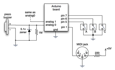
The hardware is an Arduino board with a MIDI jack, a few buttons, and two piezos attached to it. It runs off of a 9V battery.

(Note: depending on what kind of MIDI connector you’re usign (jack or cut-off cable), you may need to swap the connections to MIDI pins 4 & 5).
For the piezo input, the 1M resistor is to bleed off the voltage generated by the piezo when it is struck. The 5.1v zener diode is there to insure any large voltages don’t make it into the Arduino and blow it out.
Arduino code
The code has a few tricks that may not be immediately obvious. First is that to implement a MIDI interface, all you really need is the ability to send serial data at 31,250 bps. This is easily done with “Serial.begin(31250)“. Once that is done, a complete three-byte MIDI note-on message can be sent with three “Serial.print(val,BYTE)” commands.
The next tricky bit is that the switches in the above schematic don’t need pull-up resistors. This is because the internal pull-ups in Arduino’s AVR chip are turned on with a “digitalWrite(pin,HIGH)“. This may seem counter-intuitive, doing a digitalWrite() on an input pin, but it’s how the AVR works. The benefit is that you no longer need a resistor to +5V and the effort to wire up each additional button is much lower.
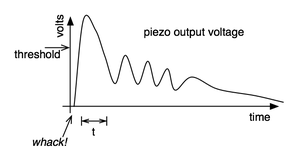
The final trick is measuring impact force on a piezo. When piezo elements are struck, their output voltage rings, sort of like a bell. Kind of like this:

By measuring the time it takes for that first big jolt to cross a threshold, you can get an idea as how big the force was. In the code this is represented by reading the analog value and if it’s over the threshold, wait until it drops down again, counting all the while. When I’ve done this before, I used an input opamp to convert the analog signal to digital (thus doing thresholding in the analog domain) and then used interrupts to get very accurate force measurements.
Arduino code: midi_drum_kit


When I connect the circuit to a keyboard, I got only piano voice instead of drum voice. Still I got piano voice also when I connect it to a PC synthesizer through a MIDI-USB converter. What is the solution for this? Thanks a lot.
Hi, is there any way to make this USB?
Hi,
I’m kinda new to all this so I was wondering which MIDI sampler is the best for use with 20 – 30 fsr or piezo inputs, each outputting a different note? Or do you thing using Processing is a better idea. Help! :S Ill be grateful for any advice I can get. :)
Thanks a lot.
Hi there:)
I made a drum set using the SpikenzieLabs Drum kit kit design, but now i want to go full scale, so i have some questions.
Let me start by saying that i have a very basic understanding of electronics and programing, so i was thinking if its possible to combine two arduino projects. The http://www.spikenzielabs.com/SpikenzieLabs/DrumKitKit.html and http://drummaster.digitalcave.ca
Can one use the 16 analog inputs of the arduino mega, use the code and serial-to-midi software from SpikenzieLabs, but add the filter to each sensor from the Drum Master, so it has better response? This way the price is kept low and the functionality is awesome.. 16 pads, oh yeah
This is Wyatt`s (drum master) approach “My final solution the filtering problem above was to use a diode, a capacitor, a couple of resistors, and an op amp (for impedance matching) to filter out the ripples, and ensure a quick voltage dropoff after the hit.”
Also if all of this is possible (im gonna try it either way, im just having trouble with the scematics), can someone please make a drawing with wires and components in the right order just for one piezo sensor, il take it from there:P (i don’t know how to read schematics). So “a diode, a capacitor, a couple of resistors, and an op amp” sounds very easy to do.. so please mates i really need help
Thanks:)
Erik, i have the same problem. Did you solve it?
Hi. I built this using a single piezo and hooked it up to my drum machine. It works but the volume levels are weird. when i hit the piezo softly it plays loud, when i hit it hard it plays soft. any suggestions?
Code:
// what midi channel we're sending on // ranges from 0-15 #define drumchan 1 // general midi drum notes #define note_snaredrum 30 // define the pins we use #define piezoAPin 1 #define ledPin 13 // for midi out status // analog threshold for piezo sensing #define PIEZOTHRESHOLD 100 int val,t; void setup() { pinMode(ledPin, OUTPUT); Serial.begin(31250); // set MIDI baud rate } void loop() { // deal with first piezo, this is kind of a hack val = analogRead(piezoAPin); if( val >= PIEZOTHRESHOLD ) { t=0; while(analogRead(piezoAPin) >= PIEZOTHRESHOLD/2) { t++; } noteOn(drumchan,note_snaredrum, t*2); delay(t); noteOff(drumchan,note_snaredrum,0); } } // Send a MIDI note-on message. Like pressing a piano key // channel ranges from 0-15 void noteOn(byte channel, byte note, byte velocity) { midiMsg( (0x90 | channel), note, velocity); } // Send a MIDI note-off message. Like releasing a piano key void noteOff(byte channel, byte note, byte velocity) { midiMsg( (0x80 | channel), note, velocity); } // Send a general MIDI message void midiMsg(byte cmd, byte data1, byte data2) { digitalWrite(ledPin,HIGH); // indicate we're sending MIDI data Serial.print(cmd, BYTE); Serial.print(data1, BYTE); Serial.print(data2, BYTE); digitalWrite(ledPin,LOW); }thank, I think it’s clearer now. Problem was I thought that, when struck, the piezo acted like a battery, not like a capacitor.
thanks again
nareto
Hi Nareto,
The piezo essentially acts as a capacitor that generates its own charge. In the schematic, if you ignore the zener diode and Arduino for a moment, you have just the piezo and the resistor. The piezo will make a charge between its “+” and “-” terminal, which the resistor will then discharge. The amount of time it takes to discharge depends on the amount of charge and the value of the resistor. Now if you add back in the Arduino, it’s connected to the “+” of the piezo, reading that build up of charge and its subsequent discharge. If the resistor were before the Arduino (in series), there wouldn’t be a path to the “-” terminal for the discharge to happen.
hello, great project, I’ll use it (as others it seems) to build a cheap midi drum pad.
Just one question: you say that the 1M resistor is to “bleed off voltage”, but shouldn’t it be in series with the piezo + to bleed off voltage, rather than in parallel as it is? I mean, as it is the voltage between “analog 0” and ground is exactly the same as between the + and – of the piezo, regardless of the resistor… or is it not?
Looking at how it is wired I thought it was a pull up resistor
thanks for the clarification (still a beginner in electronics)
renato
Hi diacri,
Thanks! I’m glad that worked out for you. I don’t think you’ll have much luck turning the analog value from the photocell into something usable for MIDI. With the laser beam, it basically becomes an on/off type of sensor (that’s what the threshold value is for). You could perhaps use another photocell to detect ambient light levels and send that as a velocity value (so the darker it gets outside, the quieter the notes). As for whether you divide by 4 or 8, analogRead() ranges from 0-1023 (1024 values) and MIDI velocity values range from 0-127 (128 values), so that means you’d want a 1024/128 = 8 division.
thank you so much. It seemed like such a simple thing to do, but was really starting to get to me because it started to look like such a complex problem.
The other thing I wasn’t sure of was whether I have to divide the analogRead by 4 or 8 to send it to digitalWrite as a midi signal?
Thanks heaps for your help. Now i’m definitely in the right direction, especially now that i know the sensor is working via a serial read running at 1004 with laser on it and reading 564 with it off.
P.s. your blog rocks socks! Just been hobbying with arduino now for a few months, and been raving about the arduino and your blog to everyone!! (even though they think i’m boring) :)!
Hi diacri,
When debugging finicky sensors, it’s really helpful to create a totally new sketch that contains just the code to read the sensor and output via Serial.print() some message that indicates you’ve read the sensor correctly. Once you get that work, you can copy that code into your main sketch.
As for your particular issue with the photocell, your code doesn’t need to be as complex as you have it. Photocells are simple analog sensors with a value that changes with light amount. So create a threshold value that above which, the laser is definitely shining on it, and below which it’s not. Something like:
int LDR_THRESHHOLD = 523; AnalogValue = analogRead(ldrAPin); if( AnalogValue < = LDR_THRESHOLD ) { // no light on it // play midi note }I was wondering if you could healp me out with this code.
What I’m trying to do is use a modified version of your set-up and the itp force sensor set-up, but use an ldr with a 1mW laser beam being shone on it, so that when the beam is broken it sends a noteOn message to middleC. been tacking my brains and been searching everywhere, and my code still doesn’t seem to work. :(
here’s the code
// MIDI trigger from LDR with constant laser stream from 1mW laser

#define midichan           1

#define note_midC     60

#define ldrAPin  0
#define ledPin     13  // for midi out status

byte note = 0;
int AnalogValue = 0;

int val,t;

void setup() {

  pinMode(ledPin, OUTPUT);
  Serial.begin(31250);   // set MIDI baud rate
}

void loop() {
// ldr with laser stream
  AnalogValue = analogRead(ldrAPin);
  note = AnalogValue/8;
  if( AnalogValue <= 127 ) {
    t=0;
    while(analogRead(ldrAPin) <= 127/2) {
      t++;
    }
    noteOn(midichan,note_midC, t*2);
    delay(t);
    noteOff(midichan,note_midC,0);
  }
}

// Send a MIDI note-on message.  Like pressing a piano key
// channel ranges from 0-15
void noteOn(byte channel, byte note, byte velocity) {
  midiMsg( (0x90 | channel), note, velocity);
}

// Send a MIDI note-off message.  Like releasing a piano key
void noteOff(byte channel, byte note, byte velocity) {
  midiMsg( (0x80 | channel), note, velocity);
}

// Send a general MIDI message
void midiMsg(byte cmd, byte data1, byte data2) {
  digitalWrite(ledPin,HIGH);  // indicate we're sending MIDI data
  Serial.print(cmd, BYTE);
  Serial.print(data1, BYTE);
  Serial.print(data2, BYTE);
  digitalWrite(ledPin,LOW);
}
hardware wise i connected the ldr the same way as the itp force sensor.
Hi.
Great Example, I have been looking for a cheap midi Pad.
This is a perfect start.
One Question:
How would I add start & Stop Button commands?
would it be as simple as:
Serial.print(0xFC, BYTE);//StopThanks in Advance
Darrell
Hi Gab, I think electronic drumpads are just piezos too. So you might be able to just wire it up in place of the piezo. So you don’t have to cut the cable of your drumpad, you can get a 1/4″ socket and wire that up, then plug the pad into the socket.
Hi todbot,
Thanks for the great tutorial!!
I was just wondering if i should modify the circuit in any way if i intended on using an actual electronic drum pad (with has a 1/4″ jack out) instead of the piezo.
Thanks!!
Hiya.
I am working on making something similar but I was just wondering about what you mentioned as a better way of thresholding. I was wondering what kind of op amp you would use, and what you mean by interrupts. Sorry I’m new at this,
Eimear
Hi Brian,
The Arduino just sees the the RN-41 as a serial port; there’s no abstraction layer beyond that. The latency is inherent to the Bluetooth connection between your computer and the RN-41. There may be some configuration options in the RN-41 or maybe your OS’s Bluetooth stack to reduce the latency. One thing I’d try is turning off encryption in the RF-41. Encryption usually adds several millisecs of latency.
I’m looking through the RN-41 AT Command Set PDF off of Sparkfun’s site and there’s a section 7.4 “Optimizing for Latency or Throughput” where they say “The default mode is to optimize for throughput.” and “Unfortunately, Bluetooth has algorithms that can cause significant latency between packets ( > 10ms) at certain times.” But they’ve got a way around that: “There is another method of optimization, which will force the radio to attempt to keep small bursts of data together. In this mode we optimize for latency. To enable this mode, there is a special debug command. The command is “SQ,16”.”
todbot,
Love the spooky arduino demo. I am trying to do something similar, only I really want to do it wirelessly over bluetooth. I’m using the Arduino pro and Sparkfun bluemate (which uses a RN-41 Roving Networks BT radio) but I can’t get the end-to-end latency low enough to be suitable for live play. I am wondering if the Arduino abstraction for using the bluetooth is inherently too laggy for the response times that I need (all you have to do is call serial.print to send BT…there has to be a tradeoff!). I believe that I need the end-to-end latency down around 20ms to make this thing usable for live drum play. And I think bluetooth in general can achieve this type of performance, e.g. Wii rock band and bluetooth keyboards/mice.
Do you have any suggestions as to how I can get the bluetooth less latent? Do I need to get different hardware that I can program bare-metal style in order to meet my latnecy requirement, or can this Arduino/Sparkfun combo be made to work somehow?
Thanks a lot,
Brian
Hi Fergo,
The zener I used in the Spooky Arduino is listed in the parts list as a
“5.1V zener diode, Jameco #179047”. But really, just about any small ~5V zener will do. Piezos do not put out very much power (just high voltages) so you’re safe getting the smallest,cheapest zener you can find.