
Spooky Projects is a set of four 3-hour classes in October 2006 hosted by Machine Project and taught by Tod E. Kurt. It is an introduction to microcontroller programming and interfacing with the real world using the Arduino physical computing platform.
In the class, participants are shown and experiment with the Arduino’s capabilities and learn the basics of common microcontroller interfacing, such as: digital output to control lights and LEDs, digital input to read switches and buttons, analog output to control motor position or LED brightness, and analog input to read sensor inputs. From these tools all sorts of interesting projects can be created. In the class, a few simple project sketches are covered using the provided parts kit, under the theme of spooky animatronics for Halloween.
The class assumes no previous electronics knowledge, though it does assume a little programming knowledge. No soldering is needed during the class, as all circuits are built with solderless breadboards.
- Class description at MachineProject
- Flickr photo set for the class
- Videos of projects
- Arduino SoCal — brand new mailing list for SoCal Arduino fans
At the end of the class, Mark Allen of Machine Project bestowed upon each of the students an awesome programming merit badge. Take other Machine Project classes to get other great geeky badges!![]()
Blog Posts
- Spooky Arduino Projects #1
- Spooky Arduino Projects #2: glowing skull eyes
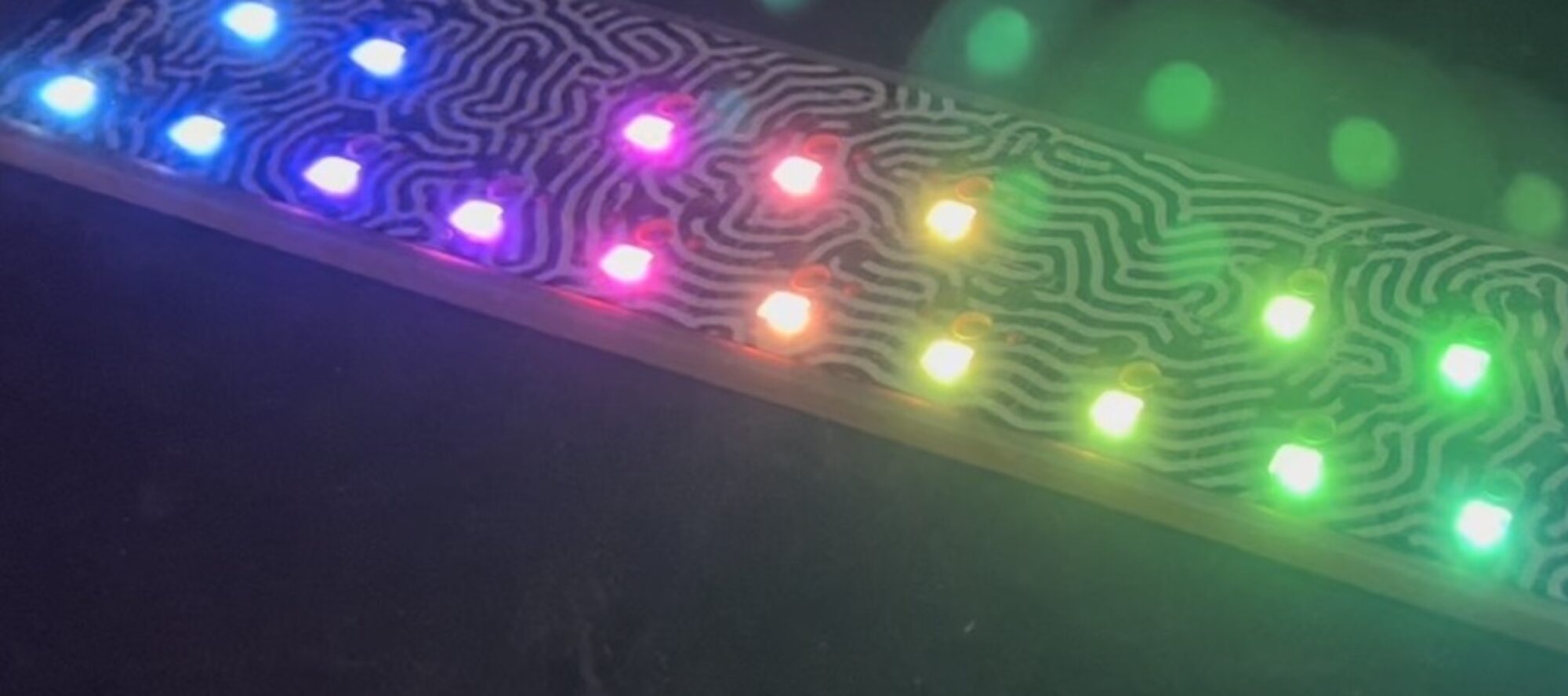
- Spooky Arduino Projects #3: RGB LEDs
- DIY Ambient Orb
- Spooky Arduino Projects #4 and Musical Arduino
Class Notes
Arduino Sketches Used in Class
- serial_hello_world — led_blink with serial printing.
- serial_read_blink — control an LED from the serial port.
- serial_rgb_led — control the RGB color mix from the serial port.
- serial_rgb_led_too — accept full “#RRGGBB” color commands. Used with Processing sketch ‘http_rgb_led’ below.
- servo_move_simple — show how to move a servo back and forth.
- servo_serial_simple — command a servo over the serial port.
- servo_serial_better — a better way to command a servo over serial.
- sound_serial — play a piezo beeper via the serial port.
- play_melody — play a melody stored in the Arduino board.
- theremin — theremin made from a photocell and piezo beeper.
- piezo_read — using piezo as a sensor, send measured piezo impulse as serial data.
- midi_drum_kit — make a MIDI drum kit using buttons and piezo triggers.
- spookarduino-sketches.zip — all the arduino sketches zipped up
Processing Sketches Used In Class
- http_rgb_led — fetch a web page, parse it, send RGB color value to Arduino. Used with Arduino sketch ‘serial_rgb_led_too’ above.
- arduino_ball — Arduino with piezo sends a number, Processing parses it and draws a ball the size of the number.
- arduino_spookysounds — When piezo on Arduino is whacked, Processing draws scary eyes and plays a spooky sound.
- spook-processing-sketches.zip — all the processing sketches zipped up
Class Kit Parts
Arduino & Other Microcontroller Resources
- Arduino-specific:
- Arduino homepage
- Arduino reference
- Arduino tutorials
- Arduino Playground — Wiki of interesting projects, intefacing Arduino with Max,Flash,etc.
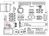
- DIY cheap Arduino prototyping shield
- ITP-related:
- ITP Intro to Physical Computing
- ITP Sensors Wiki
- Physical Computing (it’s also a book)
- General microcontroller:
68 Replies to “Spooky Projects – Introduction to Microcontrollers with Arduino”