The notes for the fourth and final class are up on the Spooky Arduino class page. At the end of the class, Mark of Machine Project bestowed upon each of the students a merit badge. It was great. Click above for a larger view of the badge.
Arduino MIDI Drum Kit and Spooky Sound Trigger
Here’s a quick project using techniques from this week’s class that turns an Arduino board and a few buttons and piezos into a MIDI drum kit or scary sound trigger. Hide piezo sensors around the house during your Halloween party to trigger scary sounds when people walk around!
Hardware
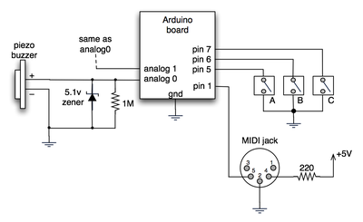
The hardware is an Arduino board with a MIDI jack, a few buttons, and two piezos attached to it. It runs off of a 9V battery.

(Note: depending on what kind of MIDI connector you’re usign (jack or cut-off cable), you may need to swap the connections to MIDI pins 4 & 5).
For the piezo input, the 1M resistor is to bleed off the voltage generated by the piezo when it is struck. The 5.1v zener diode is there to insure any large voltages don’t make it into the Arduino and blow it out.
Arduino code
The code has a few tricks that may not be immediately obvious. First is that to implement a MIDI interface, all you really need is the ability to send serial data at 31,250 bps. This is easily done with “Serial.begin(31250)“. Once that is done, a complete three-byte MIDI note-on message can be sent with three “Serial.print(val,BYTE)” commands.
The next tricky bit is that the switches in the above schematic don’t need pull-up resistors. This is because the internal pull-ups in Arduino’s AVR chip are turned on with a “digitalWrite(pin,HIGH)“. This may seem counter-intuitive, doing a digitalWrite() on an input pin, but it’s how the AVR works. The benefit is that you no longer need a resistor to +5V and the effort to wire up each additional button is much lower.
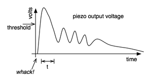
The final trick is measuring impact force on a piezo. When piezo elements are struck, their output voltage rings, sort of like a bell. Kind of like this:

By measuring the time it takes for that first big jolt to cross a threshold, you can get an idea as how big the force was. In the code this is represented by reading the analog value and if it’s over the threshold, wait until it drops down again, counting all the while. When I’ve done this before, I used an input opamp to convert the analog signal to digital (thus doing thresholding in the analog domain) and then used interrupts to get very accurate force measurements.
Arduino code: midi_drum_kit


hi, I’m phd student from turkey. I have to measure very low subsrat vibrations. I think pizeelectric sensors may be useful. how can get and record the vibrations from subtrats? thank you in advance
Hi Jack,
That sensor you link is a vibration sensor using piezoelectric material, not a piezo buzzer. They’re fairly different mechanically (the sensor is bendable, while a buzzer is rigid), so I imagine the hookup would be different.
hello !
i’m using this piezo from Sparkfun :
http://www.sparkfun.com/commerce/product_info.php?products_id=9196
Does it work like the piezo you use in your example ? (i have to use the same resistor ?).
Thanx a lot for your work.
++
Jack
wonderfull!!
My piezos are producing more than one sound at the same time. I’m using a 1k resistor. I’m not sure if the resistor has to do with this. Could someone explain to me why is this happening? I have tried with 3 different sketches and it’s still not working. Thanks.
Hi! i’m modify ardrumo project based on your project too i’ld like to create an inexpensive drum with dinamic sound can u help me to find the way to be more realistic sound over midi interface. i modifiy alla ardrumo code and now i’m able to read and play every data over usb but the sound are not real they are more eletric..please help me to find a way to have a dinamic sound over midi.
Yeah, I’m thinking you’ve got a hardware issue now too.
The “(0x90 | channel)” in this case is the same as doing “(0x90 + channel)” in this instance. The MIDI spec defines the note-on message for MIDI channel 1 as being 0x90, for channel to as 0x91, channel 3 0x92, and so on. The logical-OR operator “|” is the more technically correct way of going from the base command 0x90 to the channel-specific command. It’s like saying “start with 0x90 and then turn on these extra bits” which is conceptually different than saying “start with 0x90 and add this extra value to it”. The result in this case is the same, but you’ll run into situations where you need to make the distinction.
yeah, still not working :\
Can you explain what (0x90 | channel) is doing? The fact that it’s freezing makes me wonder if it doesn’t like my MIDI jack. I had a white cable in there that I didn’t do anything with.
Hmmm, your simpler example does note-offs with a note-on message with zero velocity (a common technique). Did you you try sending a note-off message instead? i.e. using your code:
{ ... noteOn(0×90, note, 0×45); delay(100); noteOn(0×80, note, 0×45); delay(100); } void noteOn(char cmd, char data1, char data2) { Serial.print(cmd, BYTE); Serial.print(data1, BYTE); Serial.print(data2, BYTE); }yes, the module works with my keyboard controller. i tried this simpler sketch to see if i can get anything going with no luck:
// Variables:
char note = 0;            // The MIDI note value to be played

void setup() {
  //  Set MIDI baud rate:
  Serial.begin(31250);
}

void loop() {
  // play notes from F#-0 (30) to F#-5 (90):
  for (note = 30; note < 90; note ++) {
    //Note on channel 1 (0x90), some note value (note), middle velocity (0x45):
    noteOn(0x90, note, 0x45);
    delay(100);
    //Note on channel 1 (0x90), some note value (note), silent velocity (0x00):
    noteOn(0x90, note, 0x00);
    delay(100);
  }
}

//  plays a MIDI note.  Doesn't check to see that
//  cmd is greater than 127, or that data values are  less than 127:
void noteOn(char cmd, char data1, char data2) {
  Serial.print(cmd, BYTE);
  Serial.print(data1, BYTE);
  Serial.print(data2, BYTE);
}
there’s something about the MIDI message that it doesn’t like. it must be something weird with that module, no one else seems to have that problem. everything works good with ardrumo, but i’d rather use the module. oh well, thanks anyways.
Hi Toni,
Hmm, that is weird. Have you used another device that generates MIDI with the module?
Now that I look at my sketch, I’m pretty sure I had the MIDI code for noteOn() and noteOff() wrong. I had this:
void noteOn(byte channel, byte note, byte velocity) {
  midiMsg( (0x80 | (channel< <4)), note, velocity);
}
void noteOff(byte channel, byte note, byte velocity) {
  midiMsg( (0x80 | (channel<<4)), note, velocity);
}
and it should be:
// channel ranges from 0-15
void noteOn(byte channel, byte note, byte velocity) {
  midiMsg( (0x90 | channel), note, velocity);
}
void noteOff(byte channel, byte note, byte velocity) {
  midiMsg( (0x80 | channel), note, velocity);
}
I can’t believe I had this wrong. I’ve updated the sketch to have this change.
Hi Tod,
I’m having a strange problem with my Roland XV-2020 MIDI module. I know it’s getting the MIDI messages because the MIDI light is lighting up on the module, but it isn’t playing anything. Also, the module sort of freezes – it won’t allow me to go to another drumset or anything. Any ideas on what this could mean? Thanks!
Hi Andrej,
Yup, it’s almost assuredly because of that delay, but not an Arduino limitation. It’s my code’s limitation. :) The code currently waits for a signal on any input, and when it sees one, it spins with a delay loop until the signal drops. While it’s doing that, it’s not reading any other inputs.
Better could would do the same thing but not spin waiting for the signal to drop. Instead it would remember the fact that a signal happened, and keep inputs.
Hi Tod,
First of all, thanks a lot for this great tutorial! I’ve managed to make a multi drum pad out of it and it plays very well.
I used Roland serial-to-midi driver (Windows XP) and for some strange reason I could receive midi messages in my DAW through Arduino’s USB connection (baud rate 38400) without updating the FTDI drivers to midi’s speed of 31250 (I did change them eventually though). Do you have an idea of why it worked?
Also, it seems that I can only get 1 midi message at a time: for example, hitting 2 pads at the same time results only in 1 of them sounding. Is it a problem with the code (“delay” function?) or the Arduino’s internal limitation?
Thanks in advance.
Hi Mark,
The output voltage can be very high, into the thousands of volts, both positive and negative. It’s the same material used to create electrical spark in oven starters and some lighters. The current is very low though, only a few micro-amps, and the duration is very small.
hey just wondering what range of voltage is produced by those piezo pads, just the initial pulse?
Hi Seb, Not really. The Zener diode and resistor are doing two different things. A piezo looks sort of like a capacitor (where the charge on it is proportional to how hard it was hit), so it needs a resistor to drain off the charge built up in the piezo. The trade off is if the resistor’s value is too high, the charge in the piezo goes to the max and you can’t sense anything, but if the resistance is too small, the charge drains away before you can measure it.
The Zener is what blocks the huge voltage that can potentially be produced by the piezo. In practice people often omit the Zener because the Arduino’s chip has a measure of built-in protection.
Hi,
To place a 10M resistor instead the zener/1m would be able achieve the same goal of protection ?
thanks
Seb
Yeah, don’t hook up anything TTL to anything that’s at RS-232 voltage levels. Those are +12V and -12V, guaranteed to fry something. Also, RS-232 logic levels are inverted from what TTL normally is (i.e. in RS-2323 -12V is a “one” and +12V is a “zero”; in TTL, 0V is a “zero” and +5V is a “one”)
I expect your microcontroller can output TTL level serial too.