The notes for the fourth and final class are up on the Spooky Arduino class page. At the end of the class, Mark of Machine Project bestowed upon each of the students a merit badge. It was great. Click above for a larger view of the badge.
Arduino MIDI Drum Kit and Spooky Sound Trigger
Here’s a quick project using techniques from this week’s class that turns an Arduino board and a few buttons and piezos into a MIDI drum kit or scary sound trigger. Hide piezo sensors around the house during your Halloween party to trigger scary sounds when people walk around!
Hardware
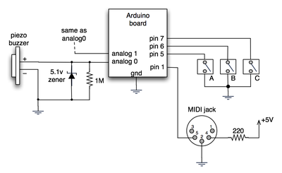
The hardware is an Arduino board with a MIDI jack, a few buttons, and two piezos attached to it. It runs off of a 9V battery.

(Note: depending on what kind of MIDI connector you’re usign (jack or cut-off cable), you may need to swap the connections to MIDI pins 4 & 5).
For the piezo input, the 1M resistor is to bleed off the voltage generated by the piezo when it is struck. The 5.1v zener diode is there to insure any large voltages don’t make it into the Arduino and blow it out.
Arduino code
The code has a few tricks that may not be immediately obvious. First is that to implement a MIDI interface, all you really need is the ability to send serial data at 31,250 bps. This is easily done with “Serial.begin(31250)“. Once that is done, a complete three-byte MIDI note-on message can be sent with three “Serial.print(val,BYTE)” commands.
The next tricky bit is that the switches in the above schematic don’t need pull-up resistors. This is because the internal pull-ups in Arduino’s AVR chip are turned on with a “digitalWrite(pin,HIGH)“. This may seem counter-intuitive, doing a digitalWrite() on an input pin, but it’s how the AVR works. The benefit is that you no longer need a resistor to +5V and the effort to wire up each additional button is much lower.
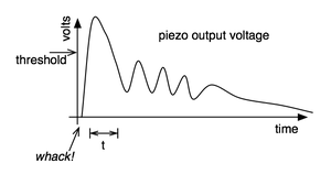
The final trick is measuring impact force on a piezo. When piezo elements are struck, their output voltage rings, sort of like a bell. Kind of like this:

By measuring the time it takes for that first big jolt to cross a threshold, you can get an idea as how big the force was. In the code this is represented by reading the analog value and if it’s over the threshold, wait until it drops down again, counting all the while. When I’ve done this before, I used an input opamp to convert the analog signal to digital (thus doing thresholding in the analog domain) and then used interrupts to get very accurate force measurements.
Arduino code: midi_drum_kit


Thanks that makes sense.
One last question….it looks like my asynchronous serial communication interface outputs have RS-232 transceivers, so from what I understand, that is not using TTL voltage levels. Will it be a problem if I use these outputs plugged into my midi/game port, or is it only a problem going the other way (TTL tx to RS232)?
Hi Ace,
Traditional asynchronous serial (what you’re calling SCI above), has two signal lines: TX and RX. One lets a device send data to another device, the other lets a device receive data. Both devices must have a previously agreed upon baud rate (the rate at which data is transmitted) and accurate internal clocks to ensure the baud rates don’t drift over time. If you’ve ever had to hook up a serial device or modem to a PC, you’ve run into the problem of baud rates not matching.
To get around this problem, you can add another signal line to the mix, which is the clock line. Now there’s three lines: Clock, TX, and RX. Every time the clock line wiggles, both sides can send or receive data. This is called synchronous serial communication, because the clock is sent along with the data. This is what SPI is. Normally, in SPI the signals are named SCLK, MOSI, and MISO. In SPI, one device is called the Master and the other is the Slave. The master creates the SCLK signal. Then, data is transmitted out from the master on the MOSI line (MOSI==”master out, slave in”). Similarly, data is received into the master from the slave on the MISO line (“master in, slave out”).
As to which to use for a particular application, it depends. SPI allows multiple slaves, so you can have many devices communicating back to the master. Normal async serial doesn’t allow for this. But async serial is usually much easier to use when it’s just two devices talking to each other. And lots of things speak it. You can get a USB-to-serial adpater much easier than you can get a USB-to-SPI adapter, for instance.
Oh and MIDI is just a kind of asynchronous serial. The main difference is that its baud rate is set to 31250 bps.
Can you explain what the difference is in the SPI vs. Serial (SCI?) interfaces?
I notice that the Arduino info says “These pins support SPI communication, which, although provided by the underlying hardware, is not currently included in the Arduino language.”
I’m actually planning on trying your example using a Motorola processor I already have, and am not sure if I should use the SPI or SCI (RS-232) pins…because I don’t understand the difference, and can’t find anything to explain it to me. It looks like your Arduino example uses what would be the equivalent of my SCI (rs-232), but I’m not sure.
Hi Ace,
Yup, you can wire up an Arduino with a MIDI out jack and run a MIDI cable between the Arduino and your PC. That works fine. The question I was answering (poorly) was using sending MIDI data over the Arduino’s USB port. For that you need a program on the PC that reads data off the “serial port” that Arduino’s USB looks like to the PC.
I’m confused about your answer above regarding sending the data to a pc:
“There’s a few different ways to go about it, but all hinge on having some program on the PC that listens to a serial port (which is what Arduino’s USB port looks like to the computer) and then triggers samples.”
What if you plug directly into a computer MIDI/Game Port?
Hi! For each input, you have a piezo, a 1M resistor, and a zener diode. (many people leave off the zener, it’s a preventative measure)
Hello!
This is cool! Thanks! :) I was thinking to make this kind of project to control MIDI things in FL Studio and other(s) music DAWs. 6 piezos should be enough, but now I can’t figure out how many and what components, I need to do this(“that”): 6 piezos I think is OK but resistors?6x? 1MOhms for each? zeners?
Any help? Thanks :)
Hi Mike,
The Arduino is configured to be a MIDI controller. It outputs MIDI over a MIDI jack. So you can hook it up to anything that has a MIDI input.
In order to hook it up to your computer, you have to do the somewhat non-intuitive thing of hooking it up through a MIDI interface (I have an old 2-port USB-to-MIDI that I used in the video)
There are efforts to turn write OS-specific drivers to turn the USB serial interface built into Arduino into a kind of MIDI interface, but the point of the sketch above was to show how to generate regular MIDI.
How is the Arduino able to output to the computer? Does it bypass the MIDI module and go straight to the computer? Or is it routed through the MIDI module? I guess I’m confused as to how a sampler on the PC would recognize the input… Can someone please clarify as to how this is done? Is it possible to output the MIDI data to PC directly and have the PC recognize and play the sounds?
Yea, Processing 0154.
Oh that’s pretty weird. I wouldn’t have expected that. I don’t use Vista so I’m not much help. Are you running the latest version of Processing?
Thanks Tod,
I created the data directory with the .wav files and it still gave me errors. I did have this working last year, only thing that changed was that I now have a new PC with vista. So I tried setting it up on my laptop that is running XP, and it works fine. So I guess there is some issue with processing and vista?
Hi David,
Yes, you create a “data” directory in the same directory as the .pde file for Processing, and then stick whatever sounds you want in there. For example, see the Processing sketch directory here:
http://todbot.com/processing/arduino_spookysounds/
and how there’a “data” directory filled with .WAV sounds.
Hi,
I’m trying to setup the spooky sound trigger you describe in your notes using Processing sketch you wrote. I keep getting an error that says unable to load spooky00.wav … It reads the serial fine from the piezo and draws the eyes, just no sounds. Any ideas? Is there a special place I need to put the .wav files? (I’ve tried everywhere I can think it would be looking for them). Thanks!
Hi Christian,
Yup, this code will work with kind of Arduino. And any MIDI interface should work, the cheaper the better in my opinion. :)
This is a really cool project. However, there s some questions,I need to ask before I make it.
I can se that you’re using an older Arduino version. would the code provided on this page work with the Diecimila?
Will it work with a really cheap midi interface like the one, I found here:
http://search.stores.ebay.com/Daily-Neccessaries_midi_W0QQfciZQ2d1QQfclZ3QQfsnZDailyQ20NeccessariesQQfsooZ1QQfsopZ1QQsaselZ429237349QQsofpZ0
wyatt — Seriously thorough!