
(as a few had noticed, I had an error in the schematic shown. It’s been updated, thanks!)
A recent question from a friend who made a really cool BlinkM hoodie was: How can you turn a momentary button press into an on/off toggle?
There are tons of ways to do this if you like getting into electronics. Most all work off of some flip-flop like principle. And while I could have suggested a true flip-flop chip, I thought it would be cooler if you could use a 555 timer chip (which contains a single flip-flop and a couple of comparators). After scouring my childhood collection of Forrest Mims electronics books and a few 555 timer devoted websites (two of the best I found were: http://www.bowdenshobbycircuits.info/ & http://www.kpsec.freeuk.com/555timer.htm), I cobbled together the following circuit based off a few almost-what-I-wanted examples.
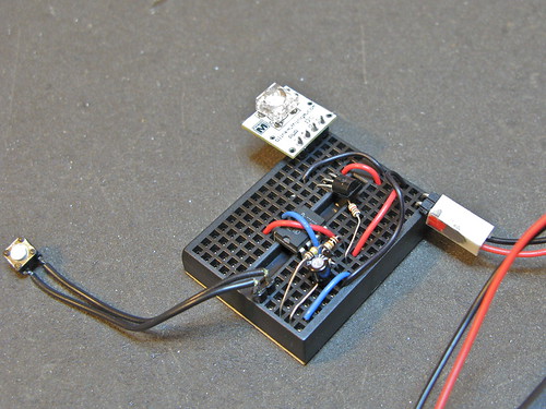
This is what it looks like in use:
The schematic is pretty straightforward, but does use a bit of feedback trickery to get the toggle functionality:
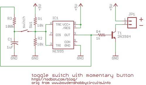
(old incorrect version here)
The parts cost is pretty low. The 555 timer chip can be had for about $0.43, the 2N3904 transistor for ~$0.40, and various resistors & capacitors are essentially free if you have them.
The circuit has 3 external two-pin connections: 5V&Gnd, button input, and the two pins of the thing to switch. In this case, the switched thing is a power supply to a BlinkM.
By changing the transistor to a beefier one, you can switch much larger loads. The little 2N3904 transistor in there now can switch around 200mA, but a bigger NPN or FET transistor and you could switch a few amps.
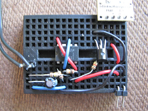
It can be made pretty small on a tiny breadboard (courtesy of FunGizmos.com) like this:
It’s not the greatest for battery-powered applications. When “off” it draws about 4-6mA, depending on the brand of 555 timer chip you use. When on it draws that plus whatever power the switched device draws. Best to put a proper power switch on the battery pack to eliminate this quiescent drain.
I made the above circuit and was testing it out using a red LED. Powering it up the LED turns on but the swicth as no efffect in turning the led off. I have gone over the connections one by one and all looks. Even tried changing the 555, but still no resolution. Your help will be appreciated. Please post and ideas or feel free to email me.
rgds
kamran
Hi there.. this circuit is very nice.. and easy to build with your instructions… im trying to activate this, with one IR tsop1838 (so it will be wireless :P ) and one transistor doing the job as switch.. but i got stuck… i can activate the led… but i cant deactivate it xD
if someone could give me some help.. im kinda newbie in electronics :/
This circuit works flawlessy! :)
I was looking for a way to switch my computer fanLEDs on and off, but the switch has to be as small as a tactile momentary switch; this circuit does the job VERY WELL!
Thanks from the Netherlands!
This 555? latching circuit is not ideal for a battery-powered devices because the standby current is 1.5mA @ 3.3V operating voltage, which is very high for a circuit that is supposed to be “off”.
how can i switch on and off this circuit with another transistor link with the output of ic lm3914…?
please help
If you fit a 2k2 between base and 0v, the transistor will always turn off.
If you fit a 100n across the upper 10k resistor, the chip will always turn on in RESET mode.
hi :) great little circuit.
ive been trying to replace the button with a transitor or an opto isolator. So the latch can be triggered from a logic 1.
i wonder,has anyone any ideas what part could replace the manual switch?
: P
This is exactly what I’m looking for but is it possible add one more push button for reset??? I mean- if circuit is switched on reset push button will all the time reset circuit and circuit stay off
Never mind, I found this website:
http://www.bowdenshobbycircuits.info/page9.htm (chapter: “Relay Toggle Circuit Using a 555 Timer”)
Thanks anyway!
perfect circuit! I was wondering if it’s possible to power it with a 12V power supply, the datasheet states that the 555 can operate at 15V…, does anyone know??
THANKS!!!
I’m a beginner, and doing an ardiuno project. for the project I needed 12v (for the arduino) 5V for a relay and 3.3 for a lcd screen backlight. so I ended up using a ATX power supply.
So I took your sketch and used the 5Vs.b. to “short” the 3.3V sp-on ….
So now I can switch the ATX on by the momentary push button … HAPPY :)
Thanks again, great post
This is exactly what I’m looking for!
Thank you! :)
(iMac G5 20″-hack into a standalone monitor – view my webpage).
i have found that using a 3906 transistor as opposed to a 3904 transistor works exactly as in the video. i had no success getting the 3904 to turn the led off. i popped a 3906 in and it worked just fine.
Hi,
Is there a 555 timer circuit which can toggle between three different states. If yes can you please post the links. It will be really helpful for me.
thanks
moralinverter
Just curious if there is a way to also keep the timer function, as in – press once, circuit is on for 1 hour then turns off or turns off immediately if pressed again while on.
Gumby,
Disconnect pin 4 from +5V. Put a 10K resistor from pin 4 to +5V and a 0.1uF capacitor from pin 4 to GND. That will give the circuit a short reset pulse when power is applied.
I was wondering, do you know of a way to make sure the circuit is always defaulting to “Off” when you power it up? I have the circuit working, but when I initially turn on the power supply I get the LED on sometimes and off sometimes, even though I have been making sure the circuit is in the off position when I power it down. I’d like this as a safety feature, but I lack the insight into that problem. Thanks in advance for any information and thanks for posting this. As a newbie I really needed to see the circuit in another form besides the schematic to make heads or tails out of it.
now ive managed to get this working however i cant seem to get this to pulse aswell, is this possible?
Basically i want this so when the tactile switch is pushed the led will flash rather than stay on.
cant seem to get it to work