
(as a few had noticed, I had an error in the schematic shown. It’s been updated, thanks!)
A recent question from a friend who made a really cool BlinkM hoodie was: How can you turn a momentary button press into an on/off toggle?
There are tons of ways to do this if you like getting into electronics. Most all work off of some flip-flop like principle. And while I could have suggested a true flip-flop chip, I thought it would be cooler if you could use a 555 timer chip (which contains a single flip-flop and a couple of comparators). After scouring my childhood collection of Forrest Mims electronics books and a few 555 timer devoted websites (two of the best I found were: http://www.bowdenshobbycircuits.info/ & http://www.kpsec.freeuk.com/555timer.htm), I cobbled together the following circuit based off a few almost-what-I-wanted examples.
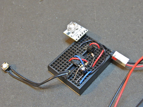
This is what it looks like in use:
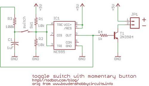
The schematic is pretty straightforward, but does use a bit of feedback trickery to get the toggle functionality:
(old incorrect version here)
The parts cost is pretty low. The 555 timer chip can be had for about $0.43, the 2N3904 transistor for ~$0.40, and various resistors & capacitors are essentially free if you have them.
The circuit has 3 external two-pin connections: 5V&Gnd, button input, and the two pins of the thing to switch. In this case, the switched thing is a power supply to a BlinkM.
By changing the transistor to a beefier one, you can switch much larger loads. The little 2N3904 transistor in there now can switch around 200mA, but a bigger NPN or FET transistor and you could switch a few amps.
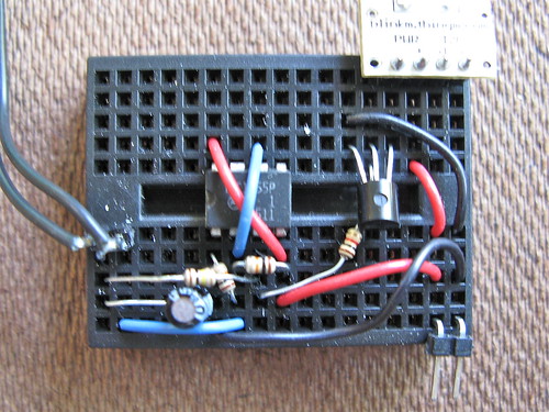
It can be made pretty small on a tiny breadboard (courtesy of FunGizmos.com) like this:
It’s not the greatest for battery-powered applications. When “off” it draws about 4-6mA, depending on the brand of 555 timer chip you use. When on it draws that plus whatever power the switched device draws. Best to put a proper power switch on the battery pack to eliminate this quiescent drain.
You can make this to a ON OFF ON switch. Some one should try, this is only bistable switch.
It is nice but how can we improve the circuit to work with a car battery?
How do you replace the switch with a sensor so that it can be turn ON when a given signal is detected for a while and turn OFF when the same signal is detected the second time. I did my own design but one has to use two 555 ICs which is not cost effective and will lead to a bit high power consumption.
I saw somebody asking how to make a 555 I C to have 3 stable states you can make two latches in which each one has two switches ON/OFF and then make OFF to become on switch for both latches while each latch is having a seperate ON switch. So as to have ON-OFF-ON.
Note:
I forgot one detail in the modified circuit. You’re going to have to modify the original external voltage divider so that pins 2 and 6 (Threshold and Trigger) sit between 1/4 Vcc and 1/2 Vcc when the switch is open. You can hold the open switch voltage at 3/4 Vcc by using a 5kOhm resistor for R1 and a 3kOhm resistor for R2.
Hey Dave,
So far as I can recall, the 555 chip can have an output of around 1.7 Volts below Vcc.
The circuit in this article needs capacitor C1 to be charged to over 2/3 Vcc to turn off.
This is probably what’s going on here – when using a Vcc of 3.7V, the output pin may only charge capacitor C1 to ~2.0V. However, since you need a voltage of 2.47V or higher to get the output to go low, your circuit isn’t going to switch off.
Luckily, there’s a way around this. Pin 5 of the 555 (the CON pin) can be used to set the threshold voltage at which the output will turn off. If we assume that the internal voltage divider of the 555 chip uses 5k? resistors, then by connecting pin 5 in between a voltage divider composed of a 10k? resistor and a 5k? resistor between Vcc and ground should give us a new threshold voltage of around ½ Vcc.
http://i.imgur.com/TfutUMN.jpg
In this case ½ Vcc corresponds to 1.85 V, meaning that our output voltage of ~2.0V should charge capacitor C1 high enough to turn the output low and switch the circuit off.
If the threshold still isn’t low enough, then you can manipulate the resistor values to get even lower threshold values. For example, you could try using a 1k? resistor instead of a 5k? resistor.
– Michael
Hi guys,
works pretty well, how can I modify this to work on 3.7volts?
I can get it to switch on, but not off again on the 3.7v?
cheers
for George,
try http://circuit-diagram.hqew.net/On-And-Off-Button(NE555)_19629.html but there is some threshold when power supply re-setted
Hello,
What if I want the cirduit to be “ON” state when I power up ? is there a “reset” on power up which grants that the satet is alwys “ON” on start?
Many thanks!
Goerge
I’ve found the solution for this circuit. With only a few modifications in the schematic diagram it’s possible to correct the problem of the “self-shoot” on the output when connecting or disconnecting the power supply, no matter how the circuit is powered, either an AC/DC adapter or a battery.
1) Pins 4 and 8 (both together), must be connected to +V through a 220 ohm resistor, adding a 4.7?F bypass capacitor from that pins to GND.
2) The seventh pin from the IC must be grounded.
3) A 5K6 resistor should be added from the base of the transistor to GND.
4) R4 in the schematic should be 10K instead of 1K.
Sorry for my poor english, i’m from Argentina.
Regards. :)
how would you have to alter the circuit if you had a 12V DC source and your LEDs were 12V 5A 60W led strips with built in resistors. I’m assuming you would need a different transistor?