This upcoming Tuesday, 9 March 2010, 8pm at Crash Space in Culver City, we’ll be having some fun quick DIY projects for you to build. Come on over and have fun with us. The project kits are $5 for CrashSpace members or $10 for non-members and you can take them home after you build them.
In the kit you get the parts to build your own Bristlebot, a tiny robot made from a toothbrush:
(consists of toothbrush, pager motor, battery, and foam tape)
and LED throwie art:
(consists of two color-changing RGB LEDs, battery, and a magnet)
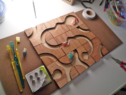
We’ll have a Bristlebot race track you can do time trials on:
And we’ll be showing you how to build all of this, no previous experience required. Come build bots and lights!
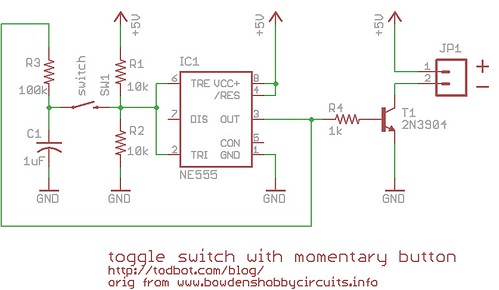
(as a few had noticed, I had an error in the schematic shown. It’s been updated, thanks!)
A recent question from a friend who made a really cool BlinkM hoodie was: How can you turn a momentary button press into an on/off toggle?
There are tons of ways to do this if you like getting into electronics. Most all work off of some flip-flop like principle. And while I could have suggested a true flip-flop chip, I thought it would be cooler if you could use a 555 timer chip (which contains a single flip-flop and a couple of comparators). After scouring my childhood collection of Forrest Mims electronics books and a few 555 timer devoted websites (two of the best I found were: http://www.bowdenshobbycircuits.info/ & http://www.kpsec.freeuk.com/555timer.htm), I cobbled together the following circuit based off a few almost-what-I-wanted examples.
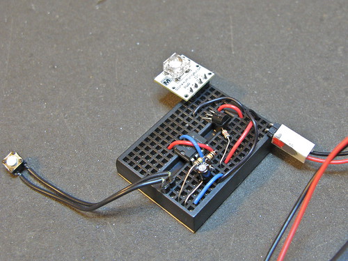
This is what it looks like in use:
The schematic is pretty straightforward, but does use a bit of feedback trickery to get the toggle functionality:
(old incorrect version here)
The parts cost is pretty low. The 555 timer chip can be had for about $0.43, the 2N3904 transistor for ~$0.40, and various resistors & capacitors are essentially free if you have them.
The circuit has 3 external two-pin connections: 5V&Gnd, button input, and the two pins of the thing to switch. In this case, the switched thing is a power supply to a BlinkM.
By changing the transistor to a beefier one, you can switch much larger loads. The little 2N3904 transistor in there now can switch around 200mA, but a bigger NPN or FET transistor and you could switch a few amps.
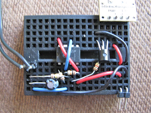
It can be made pretty small on a tiny breadboard (courtesy of FunGizmos.com) like this:
It’s not the greatest for battery-powered applications. When “off” it draws about 4-6mA, depending on the brand of 555 timer chip you use. When on it draws that plus whatever power the switched device draws. Best to put a proper power switch on the battery pack to eliminate this quiescent drain.
[This post was part of a CrashSpace mailing list discussion on a “proximity t-shirt”: a shirt that would light up or similar when other similar t-shirts were nearby. People were wondering how good RFID was at localized detection of tags.]
Okay so I’m a big RFID nerd, did a lot of consulting work using it. So here’s a quick brain dump.
Regular passive RFID is designed for identification not localization. The RFID tags can be reliably read only to within a few centimeters. But the readers are cheap. You can get 128kHz (LF) and 13.56MHz (HF) RFID readers for $20-40 and the reader chips themselves for under $2. RFID tags that work with these systems are around $1. These systems typically cannot handle multiple tags in the reader’s field at a time.
UHF (900MHz-2.4GHz) passive RFID readers can read up to a few meters, and the tags can be a $0.05 in large quantities. The readers can get pretty expensive though: >$1000. These are the systems used by Walmart et al to read a palette of Mach3 razors as they transit the warehouse. And by the marathon race timers. The standard is called EPC, if you’re interested. These systems can handle a few hundred tags in the reader’s field, but read time goes down exponentially with tag count.
“Active RFID” has ranges up to hundreds of meters. The term “active RFID” is a bit loose, since one can describe a WiFi laptop or a cellphone as active RFID tag. Really it just means an RF radio system that transmits a unique ID using its own power source. There are active RFID versions of all the above technologies. Eric’s suggested use of the RF Link boards is essentially an active RFID beacon. One of my favorite active RFID designs is OpenBeacon (http://www.openbeacon.org/ ). It uses the ubiquitous Nordic RF chips (used in almost every wireless keyboard & mouse) Sparkfun has a ton of Nordic boards to play with.
“Localization” of RFID tags can mean two things. For normal passive RFID, the tag is “located” when a reader sees it. It’s a boolean: sees it / doesn’t see it. This is often called “proximity detecton”. So one way to approach localization is to just have a lot of readers. True localization (knowing where in a reader’s field-of-view a tag is) is pretty tricky. The main issue is just finding how far away an RF source is. The simplest is signal-strength (”the louder you are the closer you are”), but that falls prey to the non-homogeneity of the environment: in free space it would work; in a room full of RF-absorbing humans, it fails. If you’re really savvy, you can do time-of-flight calculation. The reader sends out a ping and measures the time it takes to receive the tag’s echo ping. This requires nanosecond-accurate clocks on the reader (speed of light is very fast) and falls prey to multipath distortion (reflections off the environment). And then you need multiple antennae for a single region to do triangulation. It’s hard, but RFID vendors are starting to release stuff.
I have one of those USB-based logic analyzers that needs Windows software to make it go. I had been doing Windows-in-a-window with VMWare, but it’s kind of a pain. If I were to use a real Windows laptop, I’d need a shelf or something for it. I wanted it above my oscilloscope, which meant a laptop stand that was taller and wider than most. Time for the laser cutter!
(click for larger)
My design requirements were:
– assemble without any tooling or fasteners
– fit on a single 1’x2′ sheet of the 1/4″ plywood I already had
– be stable enough to hold a 7lb laptop
– be wide & tall enough for the oscilloscope to fit underneath and be usable.
The 1/4″ (0.20″ really) plywood is cheap, from a big box hardware store. I think I paid $10 for a 4’x8′ sheet of it, and they nicely cut it down to 2’x4′ sheets for me.
It ended up fitting pretty exactly on the 12″x24″ cutting bed of the laser.
I’ve been exploring various types of gearmotors. DC motors by themselves spin too fast and have low torque. Gearmotors are motors with a gearbox that slows down the high speed of the motor and produces higher torque. Most gearmotors are pretty expensive though. I want a really cheap, almost throw-away, source of gearmotors. It turns out cheap servos can be made into continuous rotation gearmotors.
Modding servos for continuous rotation is not a new hack. You can find many examples of it. You can even buy a nice continuous servo made by Parallax. But I wanted a micro servo version. I’ve been getting cheap servo motors from Hobby City, and they have several super-tiny servos for less than $4. The ones I use here are the Hextronic HXT500 available for $3.49 each.
Most cars nowadays (especially rentals, which I’ve been in a lot lately) have 1/8″ AUX inputs for an MP3 player. When I had just an iPod, this worked great. Now that I have an iPhone I found my standard 1/8″ to 1/8″ extension cable that I’ve had in my cable go bag wouldn’t work. There’s no way I’m going to spend upwards of $20 on an iPhone adapter cable to get around Apple’s design mistake. Five minutes with the Dremel and I’ve got a handy DIY iPhone adapter cable (and lots of little rubber bits all over the place)