QTPy-knob: Simple USB knob w/ CircuitPython

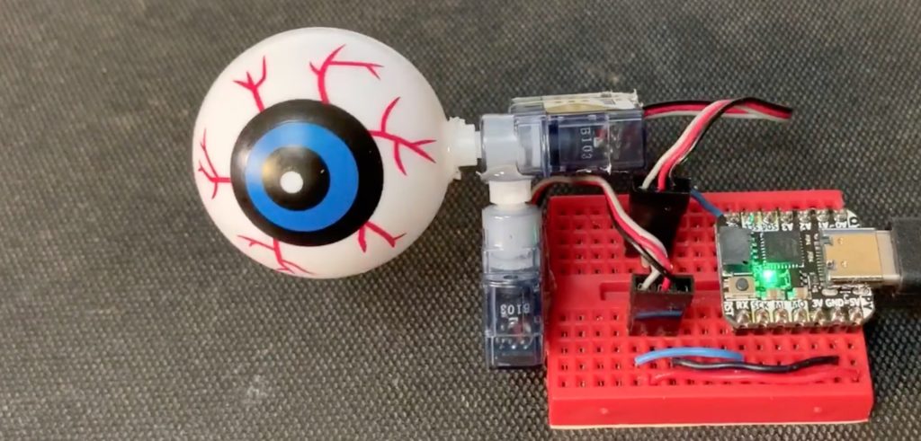
I like minimal solutions to problems. I was playing with a CircuitPython-enabled QT Py on a breadboard with and a rotary encoder and I ended up making a USB knob, like many others have done before. But I realized: waitaminute, I can literally just plug the encoder directly onto the QT Py…

Thus was born the QTPy-knob. It’s one of the simplest USB knobs I’ve come across and it’s because the happenstance that a rotary encoder can usefully be plugged directly into a QT Py board and that CircuitPython is so powerful now it’s just a few lines to go from rotary encoder pulses to sending arbitrary USB keyboard or mouse commands.

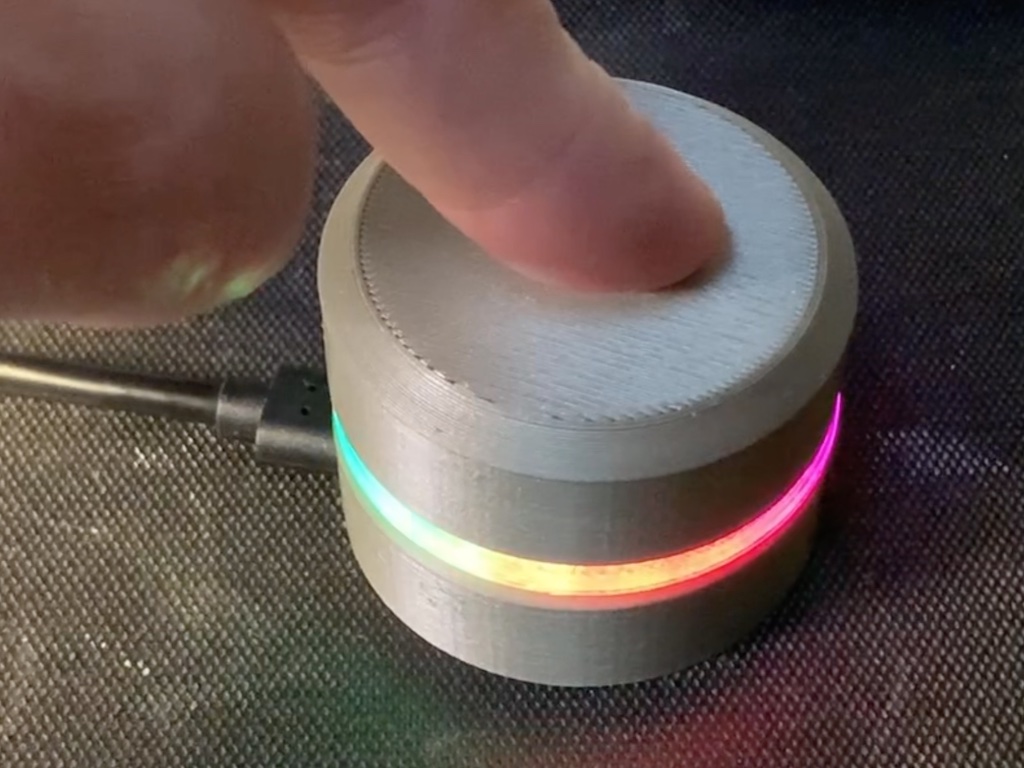
I really liked the Griffin PowerMate from over a decade ago, so I decided to design a 3d-printable enclosure that echos the design of the PowerMate, but that works with the restrictions of the QTPy+encoder stackup and a Neopixel ring. The result is pretty good I think.

All design files are in the qtpy-knob github repo.

The code is must easier now than the media-dial project I started cribbing from. This is due to the fact that CircuitPython now has native support for rotary encoders and this knob is trying to do much less than media-dial project.

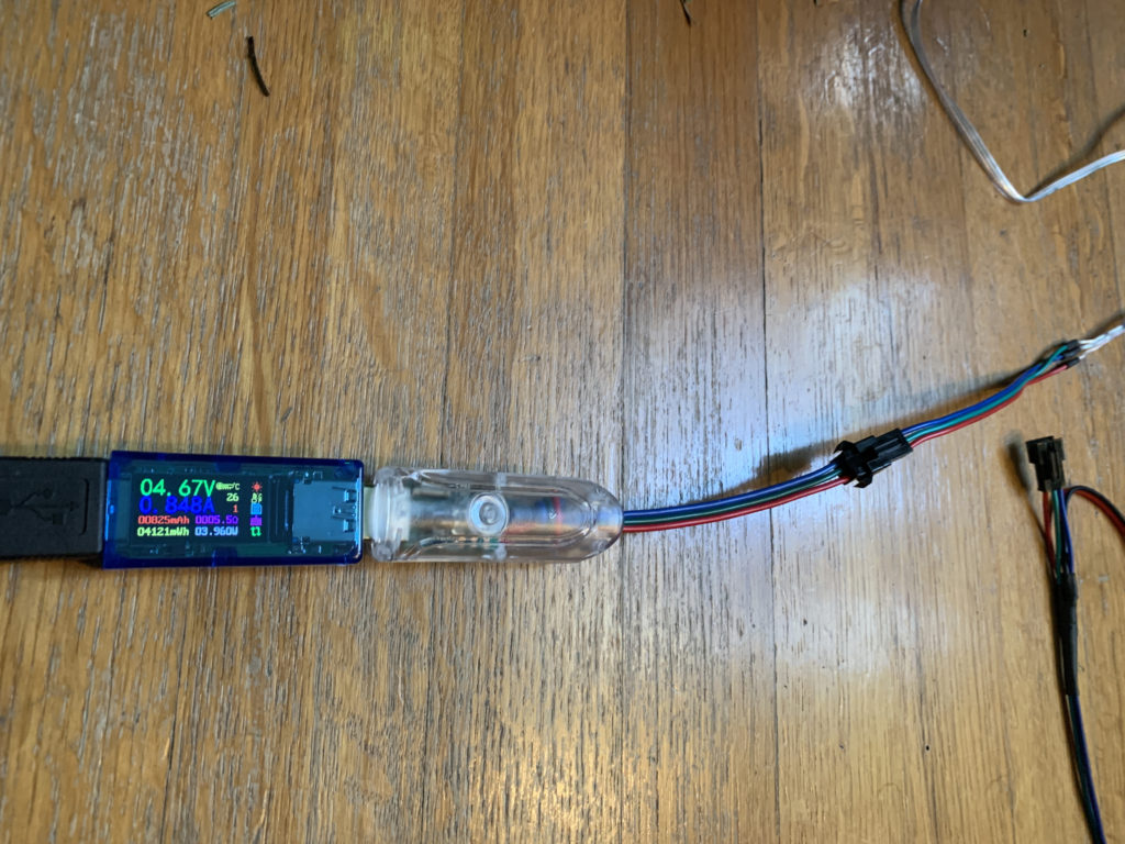
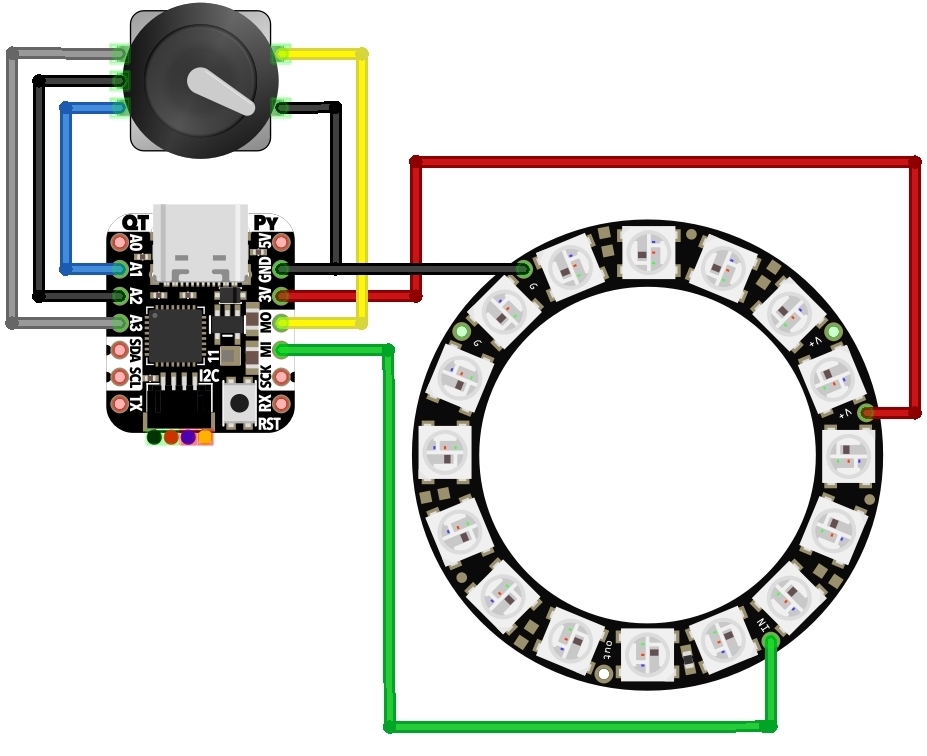
The electrical wiring is virtually non-existent, only needing three wires if you elect to add a Neopixel ring.

The assembly is described in the video above a bit, but you can also see what’s up in this CAD animation (thanks to the Adafruit_CAD_Parts repo for making the enclosure design easier)

The result with opaque plastic and clear LED diffuser ends up looking pretty cool.

DIY Neopixel / WS2812 Development Kit

If you are like me, you play around with Neopixel / WS2812-style LEDs a lot. Normally I solder my own custom-connectors and don’t use the ones that come with the reels I buy. But since we’ve been playing around with WS2812-compatible Xmas lights, I decided to make a “Neopixel Dev Kit” for easier experimenting with different LEDs and different ways of powering them. Most LED reels come with a 3-pin JST SM socket (female) connector installed with also maybe a 2.1mm DC barrel connector to inject power (see reel picture below). They’ll also throw in a pigtail JST SM plug (male) connector to attach to your controller. So I standardized on this. The kit as shown consists of (from bottom to top):

  • 3-pin JST SM socket (female) added to weird new WS2812-compatible Xmas lights
  • Known-good USB-powered WS2812 controller from those lights, rewired with JST SM plug
  • Standard 3-pin JST SM plug to JST SM socket, with 2.1mm DC barrel connector power injector
  • 3-pin JST SM plug (male) to header pins, for breadboarding
  • Known-good normal WS2812 strip with JST SM socket
  • 5V power supply with 2.1mm DC barrel connector
  • USB power meter for seeing voltage & amps drawn by any particular setup (see example below)
  • Arduino Pro Micro clone on tiny breadboard. This is a 5V microcontroller, so no need to worry about 3.3V -> 5V data issues. And it’s cheap in case we blow it up

Overall it’s working out okay. I need to add a few “sacrificial neopixels” to the mix to make using 3.3V-based microcontrollers and maybe some breadboard screw-terminals.

WS2812-compatible “fairy light” LEDs that know their address

I’ve not done much on our plotter Xmas tree this week because, well… if you follow me on Twitter, it’s likely you’ve seen me ramble on about these crazy new Christmas Tree lights we got for our tree (first tree ever!). I wasn’t able to find appropriate “Christmas Tree” light forms of the WS2812 lights, but Carlyn did! And they were even better than normal Xmas light styles. These were “fairy lights” with small beads of light connected by solid enamel-coated wire that almost disappear visually. The LED string appeared to maybe be WS2812 / Neopixel compatible and yup, they were! But the weird thing was, as I learned was discovered back in November, these LEDs remember their address when cut out of the strand. If you’re familiar with WS2812-style LEDs, this is bonkers. Normally these LEDs have four pins: +5V, Gnd, DataIn, and DataOut. To make an LED strip, the LEDs are wired in a chain, one LED’s DataOut going to next LED’s DataIn. This is great! It means you just have one wire to control hundreds of LEDs!

What’s going on with these LEDs? You cut them up, wire them in parallel (there’s no data “in” and “out”, just “data”) and they still know where they should be in the data stream, only picking the data for them. I’m still researching this with the help of some friends who can navigate Shenzhen better than me, but it’s looking like these LEDs have their address set OTP (one-time programmable) at the factory. No LED part number yet. If you’d like to get some to try yourself, here’s the 100-LED exact Amazon ASIN I bought as well as the 200-LED ASIN Carlyn originally found (both affil links).

Here’s some pics showing the box and how I took it apart to test on an Arduino Micro clone.

More Spoooky CircuitPython Circuits

Here’s two more “Spoooky CircuitPython Circuits” using the QT Py board and purposefully small programs, part of my QT Py Tricks series. Go there for the source code. The first circuit is a pair of OLED displays arranged like eyes. Behind a mask it looks really good!

The second circuit is the old trick of using capacitive touch sensors in an analog proximity mode. The result can be pretty twitchy and highly dependent on environment and power supply, but it looks good on camera! :-) And in a more defined use (like on a PCB) can give repeatable results, like the “analog” A input on my TrinketTrigger Eurorack module.

Spoooky CircuitPython Circuits!

After using Python for a decade, I’ve decided to finally get better at it. I think diving into CircuitPython will be a nice scaled-down universe to learn to write concise “Pythonic” code. For hardware I’m using Adafruit’s new QT Py board and CircuitPython’s new ESP32-S2 support. And for a theme this month I want to do “spooky circuits”, sort of a callback to my Spooky Arduino class from 2006.

I’ve been working on a “QT Py Tricks” page on github, where I’m cataloging for myself how to do basic microcontroller things in CircuitPython, in the even more reduced footprint that the QT Py and Trinket M0 boards provide (they don’t have the extra flash space that enables about half of CircuitPython’s abilities, e.g. see the support matrix)

Here’s two of the spooky projects I have so far: a tiny fire simulation and a scary servo eyeball. For the code, check out the QT Py Tricks page. Stay tuned for more!

Eurorack diversion: PT2399 Karaoke delay module hack

I’ve not been working on my Touring Machine Eurorack modular synth module, but I have been hacking a bit in that space. Back in 2019 John Park and I saw the Waveform Magazine DIY PT2399 delay module article. I got the parts and half-assembled mine, but the build guide was pretty vague in some areas so I just left it. This week I picked it up again and got it working!

The PT2399 chip is a weird little beast but is very cheap for a delay unit. The ebay listing for a fully-built PCB with preamps and jacks is <$9 (and forms the basis for the Waveform module).

Some quick hacks on it and it turns into a usable Eurorack delay module that’s also noisy and distorty, which can be fun. Here’s a little demo video of it in action:

Also to make it more usable with Eurorack-level audio signals, I added a 10k trimpot to the input jack, before the “mic2” input, kind of like the pic below. It provides you with a much more usable range on the “wet” knob before it distorts.

TouringMachine connector test

One of the benefits of having a easily-generated CAD model of a PCB with components, it becomes possible to test possible interference and clearance of connectors and cables. In this case I was worried the Eurorack power cable (2×5 IDC connector) might interfere with the micro-USB plugged into the ItsyBitsy M4. So far looks good. So I sent the board to fab and should have some to play with next week.