Or: A good use for old Arduino boards
Like me, you may have a few old Arduino boards or ATmega8 chips (in the boards) laying around from when you were first playing with Arduino. Those chips can still be really useful as the heart of a tiny “Minimal Arduino” setup.
A normal Arduino board contains support components that make it easy to use. If you want a smaller footprint, you can get one of the many Arduino work-alike boards. But if you want a really small footprint, and reuse your old parts, you can make an Arduino board using just five components:
– ATmega8 chip
– single 10k resistor
– single 0.1uF capacitor
– tiny breadboard
– some hookup wire


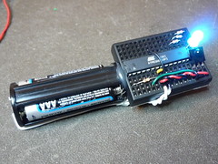
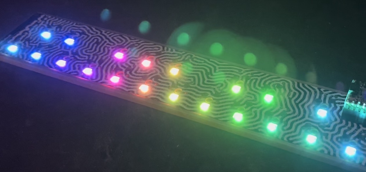
(On the left, an IR remote controlled BlinkM. On the right an IR remote controlled RGB LED)
The Circuit
The minimal Arduino circuit is dead simple. It relies on the internal 8MHz oscillator (like the Lilypad Arduino). And like the Lilypad, it doesn’t include a USB-to-serial. You have to provide that with a FTDI USB-to-serial cable or with an old Arduino board.

Eagle-format minimal-arduino.sch file
Getting the Arduino bootloader into the ATmega8
While the circuit is very similar to a Lilypad Arduino, the chip used is different. The ATmega8 has less memory and must be programmed slightly differently than the Lilypad’s ATmega168.
So a modified Arduino bootloader needs to be programmed into the ATmega8. The bootloader is a small program on the chip that listens to the serial port on power up and can reprogram the rest of the chip if instructed to. Here, a variant of the standard “Arduino NG” bootloader is used. The modifications are:
– uses internal 8MHz oscillator (no external part required)
– serial speed is 38400 instead of 19200 for faster uploads
Files for Minimal Arduino ATmega8 bootloader:
– atmega8_noxtal.zip
Unzip this file into the “arduino-0015/hardware/bootloaders” directory of your Arduino installation to create the directory “atmega8_noxtal”. The zip file contains:
– ATmegaBOOT.hex — the actual bootloader to program
– ATmegaBoot.c — the source code of the bootloader
– Makefile — Makefile to produce & program the bootloader
Actually programming the bootloader to the ATmega8 chip can be done in a few ways. I prefer using an AVRISPmkII programmer and an old Arduino board. Seat the ATmega8 into the Arduino, plug the AVRISP into the 6-pin “ICSP” header, plug both into USB, and program the ATmegaBOOT.hex file. If you are familiar with the command-line, go into the “atmega8_noxtal” directory and type “make isp” to program. If not, you can have the Arduino software program it for you once you tell it about this new kind of Arduino board.
Configuring Arduino to use Minimal Arduino
Because this minimal Arduino setup isn’t exactly like any other previous Arduino boards, we need to tell the Arduino software how to talk to it. In the Arduino directory, there is a file called “arduino-0015/hardware/boards.txt” that does this. Open that file in a text editor and add these lines to it:
##############################################################

atmega8noxtal.name=ATmega8-noxtal @8MHz

atmega8noxtal.upload.protocol=stk500
atmega8noxtal.upload.maximum_size=7168
atmega8noxtal.upload.speed=38400

atmega8noxtal.bootloader.low_fuses=0xe4
atmega8noxtal.bootloader.high_fuses=0xc4
atmega8noxtal.bootloader.path=atmega8_noxtal
atmega8noxtal.bootloader.file=ATmegaBOOT.hex
atmega8noxtal.bootloader.unlock_bits=0x3F
atmega8noxtal.bootloader.lock_bits=0x0F

atmega8noxtal.build.mcu=atmega8
atmega8noxtal.build.f_cpu=8000000L
atmega8noxtal.build.core=arduino
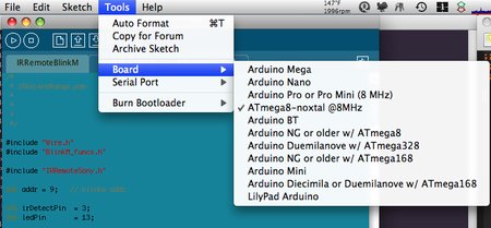
The next time you start up the Arduino software, you should have a new entry of “ATmega8-noxtal @8MHz” in the “Boards” menu. It will look something like this:
From this point you could burn the bootloader onto the ATmega8 chip by going to the “Burn Bootloader” menu and selecting “w/ AVRISP mkII”.
Uploading Arduino sketches
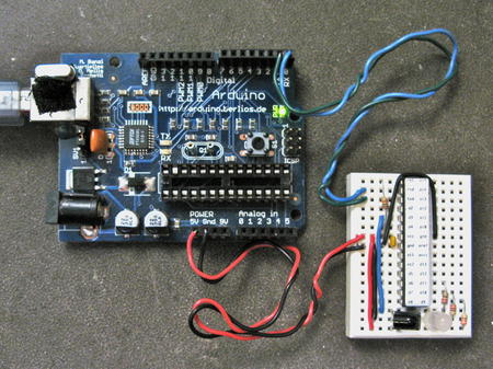
Once the bootloader has been installed, you can leave it plugged into the Arduino board to test it out, or you can remove it and place it on your minimal Arduino breadboard. To upload sketches to it, the easiest way I’ve found is to run a few wires from an old Arduino board to the breadboard:
Links / Resources
This minimal Arduino idea is nothing new. Many others have done similar things. If I could have found an Arduino clone that used an internal 8MHz oscillator on ATmega8, I would’ve used it instead. Some of the pages I referenced:
– Bootloader page on Arduino.cc
– Setting up Arduino on a Breadboard from Tom Igoe at ITP
– Standalone Arduino on the Arduino Playground
– Boarduino from Adafruit
– Really Bare Bones Board Arduino-compatible board from Modern Device
– Arduino Core Hardware page on the Arduino Playground


I had a problem with this, some error about a device signature that couldn’t be read (don’t remember it exactly).
In boards.txt, I had to change:
atmega8noxtal.upload.protocol=stk500
Into:
atmega8noxtal.upload.protocol=arduino
And now it works :)
Just tried it out (Atmega8) and had the problem that the pure breadboard version would not start. I finally solved it by grounding pin 2 (RxD).
However – nice work!
mk2
hey, nice tutorial, but i have one question can i use my serial connection if i have one (i still have a pc with a serial connection that works)
After a week of testing I keep running into a very weird problem. The only way I can get this to work is if I burn the bootloader with an STK500, then connect up my FTDI cable to the chip (while power is supplied by the STK500). At this point I can program the chip through the Arduino IDE, but the weird thing is that I can only do this 1 time after burning the bootloader. Any other time I get “avrdude: stk500_recv(): programmer is not responding” from the Arduino IDE. I don’t understand how it works the first time, but not the second.
My test is to burn the “Blink” example. The first time I do it, I change the delays to 500 so I can tell that it has worked. The second time I try using 2500 on both delays. When this won’t work, I burn the bootloader again and then (without changing anything on the arduino IDE, leaving the delays at 2500) it burns correctly. I have even tried just burning the exact same sketch twice to no avail.
I am using Atmega238P-PU chips. This is driving me nuts. I’m pulling my hair out, what am I doing wrong?
Hi, I am using Arduino Duelmilanove and when I upload there is an error message “avrdude: usbdev_open (): did not find any USB device” usb “. How do I fix this.
Tangle,
I solved this problem by uploading new sketch in a moment of starting Arduino. This is means that I turn OFF Arduino, after I push UPLOAD button and turn ON my Arduino ^^
Sorry for language, I am russian ^^
HI,
i followed all step show on this website.
when bootloader is updated,i linked a led on 13,and it blinks for 8 times.
but i can not uploading sketch to it.
can u give me some advice?
sorry for my expression,English is not my native language.
Thanks Tod for your blog,
My ATmega8 is running…
Fuses: low=0xE4 ; high=0xC2
FT232R (from Sparkfun) and a 0.1uF between DTR and the RESET.
Hi guys i still hav a problem…i ve burnt atmegaBOOT.hex into my atmega8L with the fuse values
low=0xE4 and high=0xC2
Now how to interface my uC using avrdude..? and i don wanna use arduino IDE…jus can any1 of u post the avrdude commmand line..if possible screenshots plz….thanks a lot in advance…:)
Tod, I’ve the same bugreport as the person above :)
“Also, for me the fuses that worked were low=0xE4 and high=0xC2
http://www.engbedded.com/fusecalc is a truly wonderful tool for decoding and experimenting with these.
The difference between xC2 and xC4 is the assertion for how large the bootloader space is, I think? If so, I think 0xC2 is what you want (512 words 0xC2, rather than 256 words for 0xC4)”
It seems to be an error in boards.txt snippet — the bootloader is 1K, not 0,5Kb. I’ve figured out with great help from Arduino forums:
http://www.arduino.cc/cgi-bin/yabb2/YaBB.pl?num=1289168254/13#13
Can you update, so this will save other people some time (one week for me :)).
Sorry – CKOPT should always be UNprogrammed (1) when using the RC oscillator. Pays to reread the docs :/
The value of HF = 0xda or 0xd2 is correct though (already had CKOPT=1).
Hi todbot,
I think – as others have stated – that you have incorrect fuse settings in your instructions. BOOTSZ[1..0] should be 01 for a 512 word bootloader (1024 bytes) which corresponds to the startup section in your Makefile – (8K-1K = 0x1c00), and from the datasheet CKOPT should always be set (0) when using the internal oscillator. This gives HF=0xda or 0xd2 depending on whether you want to preserve EEPROM when you flash the bootloader.
If you want an external crystal, then you can use the regular original Arduino or Arduino Lilypad .hex files, since they both used ATmega8s.
Mick, those 4-pin oscillator modules can totally be used with AVR chips. You’d want to set the CLKSEL fuses to 0000 to mean “use external clock”. I’ve not done this, but it should be possible.
Hello;
I am new to the Atmel line.
I was going through my used parts and found a bunch of oscillators.
They are 4-pin metal, pulled from various PC boards.
They have gnd/vcc/out pins.
I looked at the block diagram for the Mega128 and it seems to need two clock lines.
Can I just run a clock from this oscillator into one of them?
I have 4/8/and 16Mhz, as well as higher ones.
I would just like to get some use out of them.
Thanks
Mick M.