Or: A good use for old Arduino boards
Like me, you may have a few old Arduino boards or ATmega8 chips (in the boards) laying around from when you were first playing with Arduino. Those chips can still be really useful as the heart of a tiny “Minimal Arduino” setup.
A normal Arduino board contains support components that make it easy to use. If you want a smaller footprint, you can get one of the many Arduino work-alike boards. But if you want a really small footprint, and reuse your old parts, you can make an Arduino board using just five components:
– ATmega8 chip
– single 10k resistor
– single 0.1uF capacitor
– tiny breadboard
– some hookup wire


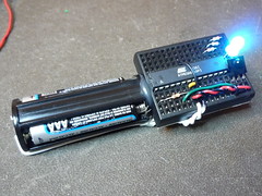
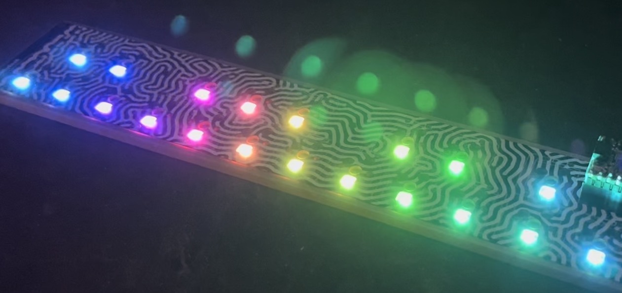
(On the left, an IR remote controlled BlinkM. On the right an IR remote controlled RGB LED)
The Circuit
The minimal Arduino circuit is dead simple. It relies on the internal 8MHz oscillator (like the Lilypad Arduino). And like the Lilypad, it doesn’t include a USB-to-serial. You have to provide that with a FTDI USB-to-serial cable or with an old Arduino board.

Eagle-format minimal-arduino.sch file
Getting the Arduino bootloader into the ATmega8
While the circuit is very similar to a Lilypad Arduino, the chip used is different. The ATmega8 has less memory and must be programmed slightly differently than the Lilypad’s ATmega168.
So a modified Arduino bootloader needs to be programmed into the ATmega8. The bootloader is a small program on the chip that listens to the serial port on power up and can reprogram the rest of the chip if instructed to. Here, a variant of the standard “Arduino NG” bootloader is used. The modifications are:
– uses internal 8MHz oscillator (no external part required)
– serial speed is 38400 instead of 19200 for faster uploads
Files for Minimal Arduino ATmega8 bootloader:
– atmega8_noxtal.zip
Unzip this file into the “arduino-0015/hardware/bootloaders” directory of your Arduino installation to create the directory “atmega8_noxtal”. The zip file contains:
– ATmegaBOOT.hex — the actual bootloader to program
– ATmegaBoot.c — the source code of the bootloader
– Makefile — Makefile to produce & program the bootloader
Actually programming the bootloader to the ATmega8 chip can be done in a few ways. I prefer using an AVRISPmkII programmer and an old Arduino board. Seat the ATmega8 into the Arduino, plug the AVRISP into the 6-pin “ICSP” header, plug both into USB, and program the ATmegaBOOT.hex file. If you are familiar with the command-line, go into the “atmega8_noxtal” directory and type “make isp” to program. If not, you can have the Arduino software program it for you once you tell it about this new kind of Arduino board.
Configuring Arduino to use Minimal Arduino
Because this minimal Arduino setup isn’t exactly like any other previous Arduino boards, we need to tell the Arduino software how to talk to it. In the Arduino directory, there is a file called “arduino-0015/hardware/boards.txt” that does this. Open that file in a text editor and add these lines to it:
##############################################################

atmega8noxtal.name=ATmega8-noxtal @8MHz

atmega8noxtal.upload.protocol=stk500
atmega8noxtal.upload.maximum_size=7168
atmega8noxtal.upload.speed=38400

atmega8noxtal.bootloader.low_fuses=0xe4
atmega8noxtal.bootloader.high_fuses=0xc4
atmega8noxtal.bootloader.path=atmega8_noxtal
atmega8noxtal.bootloader.file=ATmegaBOOT.hex
atmega8noxtal.bootloader.unlock_bits=0x3F
atmega8noxtal.bootloader.lock_bits=0x0F

atmega8noxtal.build.mcu=atmega8
atmega8noxtal.build.f_cpu=8000000L
atmega8noxtal.build.core=arduino
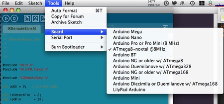
The next time you start up the Arduino software, you should have a new entry of “ATmega8-noxtal @8MHz” in the “Boards” menu. It will look something like this:
From this point you could burn the bootloader onto the ATmega8 chip by going to the “Burn Bootloader” menu and selecting “w/ AVRISP mkII”.
Uploading Arduino sketches
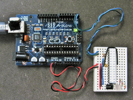
Once the bootloader has been installed, you can leave it plugged into the Arduino board to test it out, or you can remove it and place it on your minimal Arduino breadboard. To upload sketches to it, the easiest way I’ve found is to run a few wires from an old Arduino board to the breadboard:
Links / Resources
This minimal Arduino idea is nothing new. Many others have done similar things. If I could have found an Arduino clone that used an internal 8MHz oscillator on ATmega8, I would’ve used it instead. Some of the pages I referenced:
– Bootloader page on Arduino.cc
– Setting up Arduino on a Breadboard from Tom Igoe at ITP
– Standalone Arduino on the Arduino Playground
– Boarduino from Adafruit
– Really Bare Bones Board Arduino-compatible board from Modern Device
– Arduino Core Hardware page on the Arduino Playground


Hi J,
It’s most likely a fuse settings issue. Those values are very important, so make sure you program the fuses. (and make sure you have the correct value for the fuses)
Creatrope, I’m not sure what the issue is you’re having. I’m not at my bench right now so I can’t test out firmware built with the current avr-gcc compiler I’m using.
I’m trying to use your minimal arduino setup.
I’ve programmed an Atmega8 and Atmega328 (via USBtiny)
When they’re plugged into the Arduino board, they run (blink LED 12)
When I set them up alla minimal arduino, they don’t run.
I’ve checked and checked; all the pins are hooked up right, the IC is getting power to the right pins.
The only thing that is different is the capacitor I’m using. It looks like this one:
http://quality-deal.com/osCommerce/images/CAP-003D.bmp
Could that be the issue?
Hi Todbot,
Do you still have any info on optimizations/changes you used to recompile the bootloader for no xtal? I’ve started with the atmega8 directory in Arduino-0018(I assume you did as well, or did you start with the atmega168 directory that has the auto-reset in it?), changed the F_CPU to 8000000L, and tried the GCC 4.3.2 and 3.4.6 toolchain. Your bootloader works, but mine doesn’t.
–creatrope
That was the key advice!
My upload reliability is much improved. I don’t think a bootloader corruption issue was ever in play. I still don’t know for sure whether the AVR Studio hotfix applies to 4.18b700 but I’m tending to think that wasn’t an issue at all for me.
I tried quite a combinations/delays, but pressing upload in the IDE, waiting 5 seconds, THEN resetting made the difference. You’re right – there isn’t much leeway, but knowing what works +/- a second did the trick.
By the way, regarding the lockbits in case anyone else starts going down this route. Apparently only the lower six bits matter on this device, so 0xCF and 0x0F are treated the same by AVR Studio. That way you can’t do anything within AVR Studio to affect the upper two bits.
thanks! -creatrope
Hi creatrope,
Have you tried doing the trick where you press “upload” in the Arduino IDE, wait a few seconds, then power up (or reset) your board? On my bootloader firmware above, I put in a rather short time delay that the bootloader waits before running the sketch. (the original delay on old Arduino’s was around 5 seconds, mine is 1-2 I think) If there’s no sketch, the bootloader just keeps looping, looking for an upload. Such a scenario could give the results you’re seeing.
When uploading, the Arduino IDE will poll for the board for several seconds before giving up, so you have some leeway.
Thanks for doing this, I was looking forward to repurposing a bunch of Atmega8 for standalone projects. It’s *almost* working for me.
On an atmega8, I’m using E4/C4 as the fuses and setting 0xCF as the lockbits, (LPM and SPM prohibited in Boot Section).
This isn’t quite what is in your schematic (the fuses are different) but it matches the conversation in the comments which I assume are more up to date.
The lockbits on your schematic also don’t match what Miles used. Are you seeing 0xCF or 0x0F?
I’m burning your bootloader with AVR Studio 4.18 b700 and it verifies ok.
Here’s the symptom: I (usually) get exactly one good ‘upload’ (using the blink sketch) via the Arduino after each burn, and after that no contact with bootloader again via the IDE. This feels to me like the bootloader is getting corrupted, and/or sometimes inconsistently written. The odd thing is I sometimes get two good uploads.
I’ve tried with and without the bootloader hotfix (which was for AVR Studio 4.16). I cannot find any confirmation whether this hotfix is intended to apply for later versions or whether it was (hopefully) integrated into the code.
thanks, creatrope
Oh man that’s the worst, when the tools are the problem. It’s like having a screwdriver that strips screws!
Thanks for figuring this out.
Ah! I’ve figured it out. It turned out AVR Studio had a bug!
Here’s a couple of links that I found helpful:
http://www.arduino.cc/playground/Learning/Burn168
http://www.5volt.eu/archives/3
and most important the fix for AVR Studio 4.6
http://download.milesburton.com/Arduino/AVRStudio/AVRStudio16Fix_BootProgHotFix.exe [mirrored]
Yeah I did wonder that myself. Though if that were the case serial communication wouldn’t sync and you’d just receive garbage as it’s running faster/slow than expected.
I have tried burning the NG bootloader to my 168’s and that works fine (uploading sketches normally). I must say I didn’t have the same success with the AtMega 8s.
I would like to upload the bootloader in the Arduino IDE (at least that would verify the lock/unlock bits) but for some reason my STK500 clone (some cheapey off Ebay) isn’t recognised. It just sits there saying “timed out”.
Hmm, that is weird. I wonder if since you’re using a Freeduino board that has a built-in external oscillator, that the oscillator is somehow clocking the chip at 16MHz instead of doing the internal 8MHz osc.
Have you tried burning the bootloader using the Arduino IDE instead of AVR Studio? Perhaps AVR Studio is doing something with the hex file? (I notice it’s giving some sort of error in your screenshot set)
The other thing you can try, just to verify your entire process, is to burn the standard “NG” bootloader for the ATmega8 or the ATmega168. (there’s a separate one for each) That should definitely work, since your Freeduino board has the external crystal.
Hi Todbot, thanks for replying so quickly!
I’m still not having a huge amount of joy. I’m using a set of AtMega8s (and a bunch of 168 in the wings).
I’ve setup the fuses as you suggested in a Freeduino (originally housed a 328).
http://mnetcs.com/thumb/storage/b9051513.JPG
The fuses and lock bits are set via AVR Studio here:
http://mnetcs.com/thumb/storage/b9479064.JPG
Yet when I try and upload a sketch it fails. I’ve tried several different methods. Hitting reset, uploading first then reset yada yada. No joy. Theoretically it should work anyway, the Freeduino provides a reset LOW (otherwise the 320 wouldn’t work).
It’s all very strange. As I mentioned I’ve even hooked up a blinkm and uploaded the tester sketch – Fine, communication over serial is normal.
Hi Miles,
You are correct about the fuse settings being a bit off. The lfuse should be something like 0xD4, not 0xDF. Perhaps the best setting would be lfuse=0xE4. (gives a few more milliseconds to start up in case of weak power) I’ve updated the post with this change, thanks. Note that these fuse values are only for ATmega8 chips, they won’t work for ATmega88, ATmega168, and ATmega328.
I’m not sure what you mean by serial not working. Do you mean you can’t use Serial.println() and similar methods? That sounds really strange.
Or do you mean you cannot upload sketches with the Arduino IDE via a serial cable? If so, you should note that this bootloader waits a very short time looking for a sketch upload before running whatever its last programmed sketch was. It’s around a second. That means you need to apply power to the chip or reset it and then immediately hit the “Upload” button. I find it easier to hit “Upload” then power up / reset the chip, because the uploader does a few retries before giving up.
Hmm, I’ve been trying to get this going myself. Following your example I set the clocks through AVR Studio instead of Arduino (my programmer doesn’t seem to pick up?)
For some reason I can load, for example a compiled blink sketch – that’ll work fine. Uploading the bootloader you provided works but it wont respond to serial (meaning it’s pretty much useless)
Also in AVR Studio, the fuse bits seem to imply it’s using an external 8mhz clock rather than the internal 8mhz Osci.
Can anyone help?
Hi turbo,
Hmm, that’s the error you get when the AVRISPmkII programmer isn’t plugged into your system. Sometimes avrdude doesn’t recognize it, in which case I just unplug it and plug it back in. You should get a green LED light on he AVRISPmkII indicating that it’s plugged in and wired up correctly.
I’ve followed these direction but get the following error:
avrdude: usbdev_open(): did not find any USB device “usb”
i am very much a noob to AVRs. AVRstudio seemed to program the boot.hex file properly. any suggestions would be greatly appreciated. thx
This bootloader is like the original old Arduino one, where you have to press the reset button right before you upload. Since this “minimal” setup has no reset button, it means you need to apply power right before pressing upload. You have about 3 seconds after powering up to start uploading a sketch.
The official source for information about AVR fuses are in the datasheet for the particular chip you’re working with. You can go to http://atmel.com/avr/ and click on “Datasheets“. Then look for the part you’re using to get a PDF datasheet. The fuse description are in the “memory programming” section of the datasheet.
The datasheets can be pretty daunting, and the fuse section is one of the more complex. Limor started a AVR fuse tutorial. It’s only partly done, but gives some good info.
Mostly what I do is look for projects doing things similar to what I’m doing, seeing what their fuse settings are, and lookup in the datasheet what they mean. And then maybe ask someone. :) But basically, for a given circuit with a given chip, you have only a small number of potential fuse settings that will work. So if all else fails, exactly copy an existing circuit. One of the nice aspects of the many variations of Arduino and Arduino-clones that now exist is that there are several known-working circuits to copy from.
for the fusecalc tool, is there a documentation somewhere online, that explains the options, maybe even in context with Arduinos? Could you point me to anything like that?
many thanks,
Jan