I’ve been exploring various types of gearmotors. DC motors by themselves spin too fast and have low torque. Gearmotors are motors with a gearbox that slows down the high speed of the motor and produces higher torque. Most gearmotors are pretty expensive though. I want a really cheap, almost throw-away, source of gearmotors. It turns out cheap servos can be made into continuous rotation gearmotors.
Modding servos for continuous rotation is not a new hack. You can find many examples of it. You can even buy a nice continuous servo made by Parallax. But I wanted a micro servo version. I’ve been getting cheap servo motors from Hobby City, and they have several super-tiny servos for less than $4. The ones I use here are the Hextronic HXT500 available for $3.49 each.
Here’s how to modify one of those servos to make it into a tiny little gearmotor.
How it works
Servos have a pulse input that specifies what angle the servo should be positioned at. Physically, servos contain a DC motor with a gear train, a potentiometer connected to the output shaft, and control electronics that reads the position of the shaft with the pot. The control electronics compare the commanded angle and compare it to the angle read by the potentiometer, and then proportionally controls the motor’s speed depending on how close the shaft’s position is to where the servo is being instructed. By removing the pot from this loop and inserting two fixed resistors of equal value, the servo will now drive the motor continuously either forward or reverse, with a speed proportional to how far away the commanded angle is from the mid-point.
Take apart the servo.
These servos have a case made of three pieces of plastic, press-fit together. You can use a small blade screwdriver or similar thin wedge to separate the pieces. From the top you can pull off all the gears (note which ones go where). From the bottom, you can access the servo’s circuit board.
(click on any of the images to enlarge)
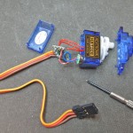 |
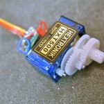 |
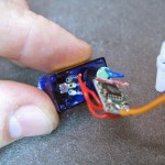 |
Remove the mechanical stops
The servo’s shaft (which is also the potentiometer shaft) has mechanical stops to prevent it from rotating too much. You want to remove these. On these servos there are two stops: one is a metal bit at the base of the shaft that can easily be bent and removed with needle-nose pliers, the other is a little plastic nub on the top case which can be snipped off with diagonal cutters.
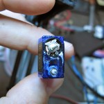
|
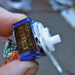
|
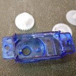
|
Replace the potentiometer with fixed resistors
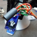
The pot in the servo is 5k. You want to replace it with two fixed resistors that add up to about 5k. I used two 2.2k resistors. I’ve also used to 2.7k in another servo. Unsolder the three wires from the servo’s potentiometer, and solder them to the two resistors. To keep this new assembly from shorting against the existing servo circuitry, tape it up, or like here, slip a bit of heat-shrink tubing over it. Then tuck it and the rest of the electronics back in the servo case and put it back together!
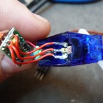
|
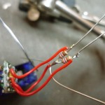
|
|
Using it with Arduino and SoftwareServo library
The sketch in the video is a real simple one that uses the Software Servo library on the Arduino Playground. On the Playground, it’s still called just “Servo”, which causes some conflict with modern Arduino. I couldn’t find a renamed version, so below is the renamed version, called “SoftwareServo”.
The SoftwareServo library is great because it lets you use any digital I/O pin as a servo output, let’s you configure the parameters of different servos, and takes an 0-180 degree angle to control the servos.
The sketch used in my tests are packed up in the zipfile SoftwareServoKnob.zip, and contains everything needed to play with servos using the SoftwareServo lib. Just unzip it and open the SoftwareServoKnob.pde file in Arduino. The files in the zip are:
– SoftwareServoKnob.pde — the sketch
– SoftwareServo.h — the library header file
– SoftwareServo.cpp — the library code file
How to “center” a continuous servo in software
One thing you’ll notice after using one of these continuous servos is that sending an angle of 90 degrees should stop the servo from spinning, but doesn’t. This is because the two fixed resistors added aren’t exactly the same value. This means that one servo might have a “zero” point at 82 degrees and another at 91 degrees. This is a pain to keep track of and is why the Parallax continuous servo contains a small trimpot that lets you adjust the zero point.
With the SoftwareServo library you can get back to having 90 degrees be the zero by adjusting the “maximumPulse” value for each servo. Create a sketch that changes the value of it with “servo1.setMaximumPulse(value)” across a range until you find a value that stops the motor when set to 90 degrees. The default value for maximumPulse is 2400, varying it between 2100 and 2700 should be enough to find the value that works for a particular servo. Remember that value (maybe write it on the bottom of the servo), use that value to setMaximumPulse on setup, and you’ve got a reversible DC gearmotor for less than $4.

Instead of replacing the potentiometer, I was able to just decouple it from the gears – I cut the pot shaft and superglued it into place so it can’t rotate, leaving it fixed at the central point. Saves two resistors and a bit of soldering!
Sorry, firewall at work will let the blog text through, but not the images (or flash). I got them by using my isp though.
Which images are you having issues with? I don’t see a problem.
What happened to the images?
Thanks for that tip, Adam. I’ve only used the SoftwareServo library, not the built-in Servo library. I didn’t realize SoftwareServo had some extra functions Servo lacked.
Thanks for the quick write up, it was very helpful to me just starting out. Good job with the pictures too, great detail!
I ran in to one problem, setMaximumPulse(value) returned an error. I looked at the library and its not in there anymore with 0015. The min and max pulse is set in attach() This is what i used to zero it out, mine happened to be off by 72ms
int minPulse = 544;
int maxPulse = 2400;
int pulseOffset = 72;
myservo.attach(9, minPulse + pulseOffset, maxPulse + pulseOffset);
This also works for the Mystery 9g servos, only you haveto chop off the top of the potmeter shaft.
Brilliant. Thank you! I’d been looking at a pile of gear reduction DC motors for a project, but was put off by their size and cost…this neatly solves both problems!
Thank you for the excellent howto. I’ve been playing with the Arduino for a couple years now, but never made anything that moves yet, because servos were so expensive. Thanks!
Not a stupid question at all. In fact, what you propose is exactly what the Parallax continuous rotation servo linked above does. I didn’t do it here because I couldn’t find a trimpot small enough to fit within the enclosure of these tiny servos. (and I could mostly fix the issue in software :)
Stupid question:
To get the servo to stop when you set it to 90 degrees, could you not just swap one of the resistors with a smaller resistor and trim pot? Then just set it to 90 and tweak the trimpot until it stops?
Nice writeup!
BTW, do you have time to post your revised SoftwareServo on the playground? We should really get rid of the one that’s still called “Servo”.
Oops, thanks. Fixed it. :)
Hi Tod,
the link to the HTX500 servo seems to have a double quote at the end, that shouldn’t be there.
Great write-up, BTW.
Cheers,
Alex