The notes for the fourth and final class are up on the Spooky Arduino class page. At the end of the class, Mark of Machine Project bestowed upon each of the students a merit badge. It was great. Click above for a larger view of the badge.
Arduino MIDI Drum Kit and Spooky Sound Trigger
Here’s a quick project using techniques from this week’s class that turns an Arduino board and a few buttons and piezos into a MIDI drum kit or scary sound trigger. Hide piezo sensors around the house during your Halloween party to trigger scary sounds when people walk around!
Hardware
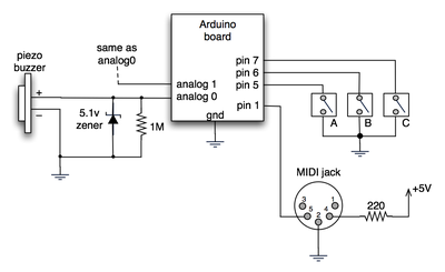
The hardware is an Arduino board with a MIDI jack, a few buttons, and two piezos attached to it. It runs off of a 9V battery.

(Note: depending on what kind of MIDI connector you’re usign (jack or cut-off cable), you may need to swap the connections to MIDI pins 4 & 5).
For the piezo input, the 1M resistor is to bleed off the voltage generated by the piezo when it is struck. The 5.1v zener diode is there to insure any large voltages don’t make it into the Arduino and blow it out.
Arduino code
The code has a few tricks that may not be immediately obvious. First is that to implement a MIDI interface, all you really need is the ability to send serial data at 31,250 bps. This is easily done with “Serial.begin(31250)“. Once that is done, a complete three-byte MIDI note-on message can be sent with three “Serial.print(val,BYTE)” commands.
The next tricky bit is that the switches in the above schematic don’t need pull-up resistors. This is because the internal pull-ups in Arduino’s AVR chip are turned on with a “digitalWrite(pin,HIGH)“. This may seem counter-intuitive, doing a digitalWrite() on an input pin, but it’s how the AVR works. The benefit is that you no longer need a resistor to +5V and the effort to wire up each additional button is much lower.
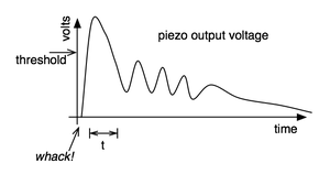
The final trick is measuring impact force on a piezo. When piezo elements are struck, their output voltage rings, sort of like a bell. Kind of like this:

By measuring the time it takes for that first big jolt to cross a threshold, you can get an idea as how big the force was. In the code this is represented by reading the analog value and if it’s over the threshold, wait until it drops down again, counting all the while. When I’ve done this before, I used an input opamp to convert the analog signal to digital (thus doing thresholding in the analog domain) and then used interrupts to get very accurate force measurements.
Arduino code: midi_drum_kit


Hi, I have followed this tutorial and im having a few issues, im new to arduino and the coding. I am trying to make a sound installation using pure data to output the received midi from my piezo’s via arduino.. now I have it all working fine but… How can I send out all of my separate piezos to different channels? Im not using this in the context of a drum kit, I have 4 piezos mounted to a metal sheet and when water drops hit the sheet it creates sound in a synthesizer. I need a simple code that will read the piezos just as it does in this code, however I use a threshold of 20 because it seems to pick up the water drops better, and output the signal through the midi cable :) I have tried to figure out the coding but I’m having no luck whatsoever. Any help would be grate guys! thanks for this tutorial!
Nice tutorial can’t wait to start mine
dbfreq, i’m doing the same thing, for I only need one trigger
but i’m pretty new to coding, would you mind sharing your code for this one
so I can be sure it’ll work, if you don’t mind?
thanks!!!
First of all excuse my poor English … This software can be installed on an Arduino Mega? All analog inputs would work? Data would be sent THROUGH USB cable?
Hello Caesar,
I used the 4051 multiplexer to make a 8 note midi xylophone. I initially had problems getting the multiplexer to work. Every time I hit a single piezo, at least three other sensors would go off. It was as if all of the input pins on one side of the multiplexer were soldered together. I wrote a program to read and print the voltage at each of the 4051 input pins and found that hitting a single piezo that was completely isolated from the others would result in high voltage readings from multiple pins. I quadruple checked my code and circuit and couldn’t find any problems. Does this sound like your problem?
I was using the # 0,1, and 2 digital pins on the arduino as select pins, and for some reason that was the source of the problem (as far as I can tell). Using the digital pins 2,3, and 4 prevented the “voltage bleed.”
Anyone have any idea why, or does that sound like bogus?
I would also check to make sure that the resistors you’re using with each piezo have the same resistance.
Hello Tod, this project served as my introdution to mico controllers. I’ve build a version using 2 or more multiplexers. My issue is that I am getting multiple notes on one sensor. I’ve seen an earlier comment about the mux sheild which is an option which is another option I had due to the number of sensors I need. However I believe I have the multiplexers wired and programed correctly. I’ve also seen concerns about impedance matching could this be the reason for this abnormal behavior ? Any suggestion ? Thank you in advance
Pitchoilcan
Joey,
If you use the Arduino “internal pull-up resistor” trick as in the sketch, you don’t need real resistors.
SleepingRico,
You can totally connect standard digital drum pads to this circuit and it should work. I’ve not done it, but I’ve heard of people doing it. The pads supposedly just have a piezo element in them.
dbfreq,
Yes, the timing problem makes the responsiveness not very good. To make it better, you need to get rid of the spinloops (those “while(analogRead())”) and any “delay()” functions. Check out the “BlinkWithoutDelay” tutorial for the basic concept of doing that.
Hey there, how are ya? I’m working on a midi drum kit using a converted remo practice pad fitted with a piezo pickup and an arduino – with its midi out going through a midi to usb converter (the kind you can buy for about $5, very generic). I’ve taken your code and stripped it back for just a single piezo – no switches or anything extra, just to experiment..
I’m wondering about the velocity sensitive part of your code.. and the time it ends up sucking up between midi events. Is there anyway to get the whole thing to work faster, say to allow for flams?
Hi there,
Can the piezos you connected to the Arduino board be replaced by standard audio jack inputs? I’m planning to connect a kick drum pad to the board, thanks to those inputs, in order to convert the audio signal into MIDI data, could this work?
Cheers
Rico
Hello,
I’m in just a similair project like this.
I was just wondering if the buttons (A B C) will need any kind of resistors or can just be connected just like in the circuit as you have posted above.
Hopefully you can help me.
with kind regards
Joey
Hy. I’m new to Arduino, but it was just what i was looking for. I also want to build a MIDI drum controller but I wan’t to use it with my computer.
The Arduino Mega solves the “more than 6 drumpads problem” but i read in the coments that MIDI dosen’t go all that well with USB. Is it possible to use a MIDI to USB cable to do the job?
Also, in the drumkit code I found these:
// general midi drum notes
#define note_bassdrum 35
#define note_snaredrum 38
#define note_hihatclosed 42
#define note_hihatopen 44
#define note_crash 49
How about if I need a lot more notes…say 16. I’m a little bit confused here, since the drum software I use har a variety of drum sounds. How are the drumnotes actualy defined?
Thank you.
Hi Luka,
– If that Kawai GMega has a MIDI input jack, then it should work fine.
– If you need more than 6 inputs, then you can either use an Arduino MEGA or use an analog multiplexer chip like the 4051.
– I’m not sure of the _best_ way to hook up a drum pedal to this, but what some people do is stick the piezo sensor on one of the surfaces that is getting hit. In the case of a bass drum, sticking it to the drumhead would work. For the hi-hat, I’m not sure. People have done it though, I’m sure. :)
Hello. I’m trying to make an electronic drum kit, but I’m not really that familiar with MIDI, so I have a few questions:
-Would this work when plugged in a Kawai GMega synth module?
-I would hook up all the pads with piezo buzzers, so what should I do if I wanted to make more than 6 pads (the max. number of Arduino analogue pins being 6)? Could I use a digital pin for some pieces of the set, or maybe somehow plug in more than one pad into one Arduino analogue pin?
-What would be the best way to connect a bass drum (or hi-hat) pedal to this (and could that be made analogue so it detects the strength of the hit)?
Thanks in advance.