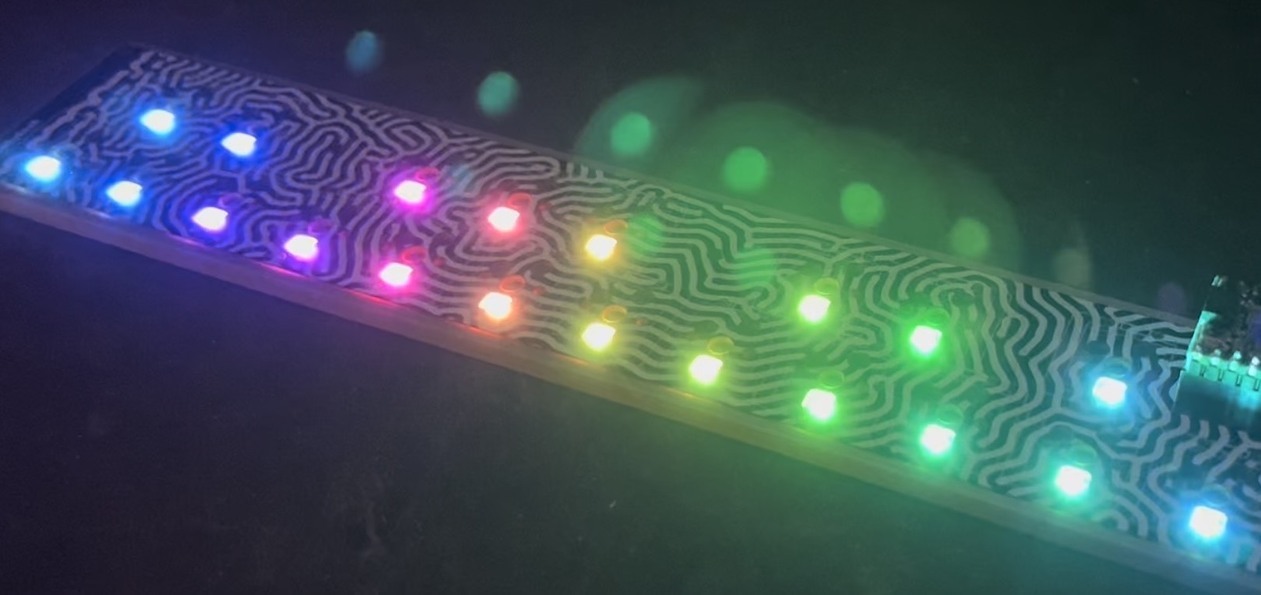
There’s been some confusion as to whether or not the DIY RGB orb presented in the last post was actually connected to a computer and receving color data from it. Here’s a video that more accurately depicts what’s going on and all the code used to create it.
Hardware
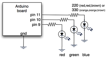
The hardware is just an Arduino board connected via USB to a laptop. The Arduino appears as a serial device to the computer. On the Arduino board, three LEDs (red,green,blue) are mounted directly to the Arduino board using a prototyping shield like this DIY one. The schematic is quite simple:

Arduino code
The code sketch running on the Arduino board is a slightly modified version of the one presented in the last Spooky Arduino class. Instead of parsing single color values over the serial port, it expects a full RGB color value in standard web format of “#RRGGBB” (white is “#ffffff”, blue is “#0000ff”, and so on). The sketch parses that seven character string into three bytes: one each for the brightness values of the red, green and blue LEDs.
Arduino code: serial_rgb_led_too.pde
Processing code
To bridge between the Arduino and the Net, a small Processing sketch was created that uses the standard Java HTTPURLConnection class to fetch a web page (really, a text file on a web server) containing a line with a color value in the format “#RRGGBB”. The sketch parses the color value, sends the value out to the Arduino orb using the Processing Serial library, and then sets its own background color to match. Because I’ve set the framerate of the sketch to 1 fps, it takes a second for the background to match the orb. I did this on purpose so I could get a sense of the color as the orb reproduces it before seeing it as it truly is. I was surprised how well the two tended to match!
Processing code: http_rgb_led.pde

Tod,
Take a look at the datasheet for those LED’s (or ones with similar shapesa nd power specs) if you can find one. Yes, red is brighter (lumens on the datasheet). Your color calibration choices are:
1. Vary the LED’s resistor (a large resistor on the Red to make it dimmer)
2. Trim pots (I like that idea, it’s elegant) on each LED
3. Modify your code with calibration fudge factors so at “FF” you are actually sending less than 5v (or whatever) to the Red LED (easiest if not incredibly elgant)
Hi Zain,
The LEDs I’ve seen that draw more than about 40mA each are the special 1W or 5W power LEDs, like by Luxeon. I’ve not had much experience with them, but these LEDs require special constant-current drivers. You definitely can’t just hook them up to the Arduino. I’ve been wanting to play with them but I just haven’t had the chance. If you do, let me know, I’d love to see what you come up with.
After doing some Googling, it looks like this guy has had some experience with LEDs similar to what you’re talking about.
Hi Tod
Your circuit works great with a prototype lamp i’m building. The current circuit runs on 14 to 20ma for standard leds. Is there way to swap out the leds for brighter ones that run on 2.5v to 3v 350ma? I’m assuming i’ll have to power the leds from a external power source, but can i still use the arduino to control the brightness of the 350ma leds?
A million thanks
Zain
Hi Laya, ” which has several examples of network-connected Arduinos. Also my Roomba books (like above right) has similar examples, in the context of hooking up to a Roomba.
I think it should be possible. There are a few gotchas. On the hardware side, the serial port on that thing is 3.3V, so you’ll need 5V-3.3V converter circuitry. Sparkfun.com has a tutorial on that. On the software side, to make it a client, it has a mode for that but it wasn’t obvious to me from the datasheet how to use it. You’ll also have to implement HTTP yourself, which isn’t that hard, but still. I recommend picking up Tom Igoe’s book “Making Things Talk
Hi Tod,
I am currently working on a project similar to what you did with the Arduino, except that I would like to add wifi to it to make it more autonomous. I was thinking I could use this wifi module : http://www.eztcp.com/en/Products/ezl-80c.php
Do you think it can be possible ? The main idea would be the same, go to a website, fetch a color code, decode it and display it using the leds.
Thanks in advance for your answer :-D
Hi Lauren,
In Processing, the extra ‘ff’ is the transparency (or “alpha”) of the color, ‘ff’ means fully opaque.
You don’t mention how you’re getting the “ffff3333” value, and if it’s a String or a number. If it’s a number, you should be able to do something like:
myval = myval & 0x00FFFFFF;
to strip off the leading ‘ff’. You can do a similar thing with Strings.
Another way is to get the individual color components with the red(), blue(), and green() commands, though I’ve not used those.
hi tod, i am currently working on an architecture project that uses processing and arduino. i am very new to both; i have been working in processing for two weeks, and arduino for three days…. right now, i have a processing sketch that generates a fluctuating color field. i want to export the effect using arduino. starting small, i am attempting to take the color value of one pixel from the field, which is constantly changing, and export that to an arduino program controlling a set of led’s. at the moment, i am using the get function to obtain the rgb values of the pixel and converting that to hex code, but it is giving me a value with two additional “f”s attached to the front. (ex: ffff3333). your arduino lessons have gotten me this far, if you could help me figure out this last bit, i would be truly grateful!
thanks tod (sorry for the tom above! :P ) i just realized that this orb was meant to work online – so my question was totally out of its element! :)
anyway once more, thanks for sharing your knowledge on arduino – i’m one of the many who always felt actracted but never dared to approach this stuff… cheers again!
Hi Pierlo,
Yes, the Arduino can run totally stand-alone. It’s a little computer you program. It can even run off a battery if you want.
So you could write a program that does some sort of color sequence, upload it to the Arduino board, then unplug the USB cable, plug in a 9VDC wall wart power supply, and it’ll keep running its program until you turn it off.
Hey tom! Thanks for this great toot. I’m a total newbie but i just fell in love with this arduino thing and i definitely want to give myself a chance.
Now the question (it might be real stupid i know, but again, excuse my noobiness) : is it possible to let this orb run on its own without any pc feeding the color-change data? It should be even easier as a starting project, am i wrong? (or maybe i totally missed the point – and the orb was MEANT to be fed with data from a pc…) Greets from Italy!
Wow, thanks for the quick reply. I have another blue LED but was thinking that I should keep them all even – so I guess I’ll add that and see if it balances out the color enough.
Hi Tom,
As long as each pair of LEDs is in series and you have the current limiting resistors in there you won’t burn anything out. Actually what will happen if you use the same value resistors (220 ohm) is the LEDs will be a little dimmer and you may not be able to get the two blue LEDs to light. You can reduce the resistor values to something like 100 ohms if you have two LEDs.
LEDs burn out by having too much current run through them. Check the datasheet for your LEDs, but most can’t take more than about 20mA (0.020A). To determine how much current (“I”) you’re supplying, use the equation:
I = (5 – Vled) / R
or to determine what value resistor “R”:
R = (5 – Vled) / I
The “5” is the 5 volts of your power supply and “Vled” is the “voltage drop” of your LEDs. For a single red LED, Vled is about 2.0 volts, and for a single blue LED, Vled is about 3.6 volts.
When you have two red LEDs the Vleds combine. You can see a problem where two blue LEDs make a Vled of 7.2 volts which is greater than your power supply. So that probably won’t work.
But for two red LEDs, the combined Vled is 4.0 volts, and thus for a 20mA current draw the resistor value you’d need is:
R = (5 – 4.0) / 0.020 = 50 ohms
The closest standard value is 47 ohms, but to be safe, use the next standard value: 100 ohms.
So, I’m working on this and right now, I only have 3 x 2 LEDs – just 2 of each color. If I wire it up and run it, will that burn out the LEDs? Or is there a way to avoid that?
Thanks!
thanks for the quick response, and keep up the good work!
Hi John,
I use the “Arduino USB Board”. I think it’s considered the archetype for the concept of “Arduino board”.
The “Arduino Serial USB Board” is poorly named. It’s just a USB-to-serial converter and is the companion to the “Arduino Stamp”. The combination of a Arduino Stamp + Arduino Serial USB Board equals the functionality of an “Arduino USB Board”.
In short, get the “Arduino USB Board” unless you need something smaller.
I have a question about which arduino board you are using in your light orb project…
http://www.sparkfun.com/commerce/categories.php?cPath=2_103
is it “Arduino Serial USB Board” or “Arduino USB Board”?
Im guessing its the serial board, but i wanted to check before I bought one…
In that case, I have a problem..I follow exactly how the Spooky Arduino project #3 instruction..how the LEDs and resistors are pin..i tried to used the code from this site and from the tutorial. Nothing light up.