There’s been some confusion as to whether or not the DIY RGB orb presented in the last post was actually connected to a computer and receving color data from it. Here’s a video that more accurately depicts what’s going on and all the code used to create it.
Hardware
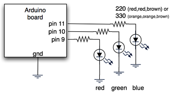
The hardware is just an Arduino board connected via USB to a laptop. The Arduino appears as a serial device to the computer. On the Arduino board, three LEDs (red,green,blue) are mounted directly to the Arduino board using a prototyping shield like this DIY one. The schematic is quite simple:

Arduino code
The code sketch running on the Arduino board is a slightly modified version of the one presented in the last Spooky Arduino class. Instead of parsing single color values over the serial port, it expects a full RGB color value in standard web format of “#RRGGBB” (white is “#ffffff”, blue is “#0000ff”, and so on). The sketch parses that seven character string into three bytes: one each for the brightness values of the red, green and blue LEDs.
Arduino code: serial_rgb_led_too.pde
Processing code
To bridge between the Arduino and the Net, a small Processing sketch was created that uses the standard Java HTTPURLConnection class to fetch a web page (really, a text file on a web server) containing a line with a color value in the format “#RRGGBB”. The sketch parses the color value, sends the value out to the Arduino orb using the Processing Serial library, and then sets its own background color to match. Because I’ve set the framerate of the sketch to 1 fps, it takes a second for the background to match the orb. I did this on purpose so I could get a sense of the color as the orb reproduces it before seeing it as it truly is. I was surprised how well the two tended to match!
Processing code: http_rgb_led.pde

Hi Clara,
Oh definitely. The prototyping shield is just a specially-shaped breadboard. I think most people use Arduino with a regular breadboard. I just like the shields because I like the compactness & having it be handheld.
Hey tod,
Sorry, is me again..Does it work without Arduino prototyping shield? Can i just use a breadboard and Arduino board instead?
Thank you for your respond~!! I’ll try it out^^
Hi Clara,
From the parts you’re concerned about, I assume you’re building the $10 Arduino prototyping shield.
For the 8-pin inline header socket, you can use Jameco’s 12-pin female header receptacle and just break off the 4 pins you don’t need.
As for the 8-pin inline wire-wrap socket, as you suspect, you can use Jameco’s 16-pin dual-inline wire-wrap socket and break it in two to get two 8-pin inline sockets.
Get a pair of good wire cutters from Jameco and the breaks will be relatively clean. (And I recommend having two cutters: one used only for wire and another used for these kinds of modifications).
As you can see, you end up “customizing” parts to fit your task. It ends up looking a little funky sometimes, but it’s electrically sound. If you need something more professional looking, you can buy appropriately-sized connectors from larger suppliers like Digikey or Mouser.
Good luck and have fun playing with Arduino!
I need help on working on this project. I can’t find a single 8 pin header socket and 8 pin inline wire-wrap socket. But i did found online at jameco website the SOCKET,SIPP,20PIN,MACHINE and SOCKET,IC,16PIN,WIRE WRAP,GOLD. Can I cut those to 8 pin?? and where the resistor and LEDs pin to? I understand red on 9, green on 10 and blue on 11..
PLS RESPOND TO ME ASAP!! THANK U VERY MUCH
I am sorry ..i am new to this..
Hi Tod,
Thanks for the quick reply :o) It works perfectly!
Hi Nicolai,

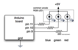
Yup, you can use common anode RGB LEDs just fine. In the circuit you connect the common anode to +5V, then run the cathode for each color to a resistor, and each resistor to a pin on Arduino. Essentially it’s the “flipped” version of the circuit above. Like this:
In the software, the
analogWrite()function is also flipped:analogWrite(redPin,0)will turn on the red LED to max brightness, andanalogWrite(redPin,255)will turn it off.To keep the code working the same, change the three analogWrite() lines to flip the color values around:
    analogWrite(redPin, 255-(colorVal&0xff0000)>>16 );

    analogWrite(greenPin, 255-(colorVal&0x00ff00)>>8 );

    analogWrite(bluePin, 255-(colorVal&0x0000ff)>>0 );
And yeah, color mixing is hard. Our eyes respond to different colors differently. And the different LED parts of an RGB LED have different brightness outputs (that don’t match our eye’s responsiveness usually), and our perception of different brightness levels isn’t linear. It makes for a tough problem.
Hi, thanks for at great tutorials :) I have been playing with your sketches with 3 individual LEDs and it works, but it’s quite difficult to get the light to mix propperly. So I got an RGB LED, which unfortunately has a common anode. Is there any way to use that?
The frosted sphere is made of glass. It’s a lamp from Ikea, cost about $8.
And yup, an RGB LED would work great. To match the circuit above you would use a common cathode RGB LED.
For this application, it doesn’t matter if it’s 3 discrete LEDs or one RGB LED. If you’re aiming for the brightest solution, you can generally get discrete R,G,&B LEDs that are brighter than a single RGB LED. Part of this is due to heat dissapation issues with all three LED dies in one case.
Where do you find the actual plastic sphere casing you used?
Also, can this be done with an RGB LED? any advantages/disatvantages?
Hi Jona,
If you’re wiring LEDs in parallel, make sure they each have their own current limiting resistor. There’s small variations between LEDs that could cause weirdness if they’re driven from a single resistor. The other problem is that the Arduino (and all microcontrollers) doesn’t really have power available to light up more than one LED per pin. To get around this you use a transistor that switch a higher current. An example of this circuit can be seen on the Cylon Roomba page. For your use, leave off the capacitor.
The Arduino appears like a normal serial port to the OS. Your desktop application could open each serial port it thinks might be an Arduino, send some sort of query (maybe just “?”) and the Arduino would send back a prearranged response (like “!”). As you iterate through all serial ports, opening them / sending the question / looking for the response, you’ll eventually find the Arduino. This is how some modem comm programs look for modems: they send “AT” to all serial ports and look for “OK” responses. Once they get that, they send other “AT” commands to determine the capabilities of the modem.
Tod,
I am making an Orb, using your method as my model, for displaying the load level of a software application ay my office. Your design fits pretty much exactly what i need to do: have a desktop application fetch the current load number from the system being monitored, send that value to the Arduino (Orb) via serial, and the Arduino addjusts its LEDs accordingly. Easy peasy, right?
Well I have a couple of questions for you about this that I need to work out before I can be successful.
First of all, I am looking at wiring 4 LEDs of each color together in parallel so that the light level will be bright enough in day time office conditions to be visible; do you see any issues with this?
Secondly, is there anyway that the Arduino could identify itself to the desktop application (or PC) when it is plugged into the USB port? I am thinking that the desktop application would allow the user to set which port the Arduino is on, but if the Arduino doesn’t identify then the user may have no clue. I have been searching for serial handshaking information but am not finding anything.
Any information or ideas you might have would be very helpful.
Jona
nice job Tod!
I am gonna have to make one myself!
spongeboy, definitely try out using capacitors as low-pass filters. You’ll need one per LED. If you’re not changing the colors very quickly (like strobing), then you can use really big ones. You may want to add a diode between the Arduino and the capacitor so the cap doesn’t discharge back thru the Arduino.
As for multiplexing, if you can switch your multiplexer fast enough (faster than your capacitors discharge for instance), I think you can run several orbs “simultaneously”.
Thanks.
I’m going to order a Arduino and do some tests. Some pre-lim research suggests trying
a) using a cap as a low pass filter to smooth the flicker.
b) multi-plexing (but this would only allow 1 orb to operate at a time.
Keep up the good work, it’s inspiring!
spongeboy: in theory yes, but you’d have to do the PWM (brightness control) for the other three orbs by hand. This is not a simple thing and you’d have to write some pretty clever C code to do it without it flickering.
So with the Arduino boards having 12 digital pins, you could have 4 orbs together? Or would the power consumption be too great?
Hi Tod,
Thanks for sharing all this greatness with us. Just started to play around with Arduino and I find your spooky projects very helpful to get some proper insights into Arduino and get up to speed.
Thanks!
You’re doing a great job with the spooky Arduino Proyects! I just post to ask how do you make electric graphics like the one in this post.
Thank you and keep workin’!