
![]()
The notes for the fourth and final class are up on the Spooky Arduino class page. At the end of the class, Mark of Machine Project bestowed upon each of the students a merit badge. It was great. Click above for a larger view of the badge.
Arduino MIDI Drum Kit and Spooky Sound Trigger
Here’s a quick project using techniques from this week’s class that turns an Arduino board and a few buttons and piezos into a MIDI drum kit or scary sound trigger. Hide piezo sensors around the house during your Halloween party to trigger scary sounds when people walk around!
Hardware
The hardware is an Arduino board with a MIDI jack, a few buttons, and two piezos attached to it. It runs off of a 9V battery.
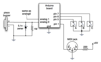
(Note: depending on what kind of MIDI connector you’re usign (jack or cut-off cable), you may need to swap the connections to MIDI pins 4 & 5).
For the piezo input, the 1M resistor is to bleed off the voltage generated by the piezo when it is struck. The 5.1v zener diode is there to insure any large voltages don’t make it into the Arduino and blow it out.
Arduino code
The code has a few tricks that may not be immediately obvious. First is that to implement a MIDI interface, all you really need is the ability to send serial data at 31,250 bps. This is easily done with “Serial.begin(31250)“. Once that is done, a complete three-byte MIDI note-on message can be sent with three “Serial.print(val,BYTE)” commands.
The next tricky bit is that the switches in the above schematic don’t need pull-up resistors. This is because the internal pull-ups in Arduino’s AVR chip are turned on with a “digitalWrite(pin,HIGH)“. This may seem counter-intuitive, doing a digitalWrite() on an input pin, but it’s how the AVR works. The benefit is that you no longer need a resistor to +5V and the effort to wire up each additional button is much lower.
The final trick is measuring impact force on a piezo. When piezo elements are struck, their output voltage rings, sort of like a bell. Kind of like this:
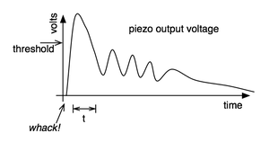
By measuring the time it takes for that first big jolt to cross a threshold, you can get an idea as how big the force was. In the code this is represented by reading the analog value and if it’s over the threshold, wait until it drops down again, counting all the while. When I’ve done this before, I used an input opamp to convert the analog signal to digital (thus doing thresholding in the analog domain) and then used interrupts to get very accurate force measurements.
Arduino code: midi_drum_kit
hi, how would you compare the arduino based with the commercial ones like vdrums or maybe the ones from edrum(also a diy)
Hi Enok,
A 9V battery should work fine. It’ll probably last for around 10 hours of continuous use.
I’m not sure which analog multiplexer works that you’re using. It must have really high input impedance (around 10 Mohms) so you can sense the piezo’s output voltage.
Hi, I’m so happy to see this great project!
Should I use a 9v battery instead of 5v usb connection?
It is very picky to control the piezo output voltage.
I’m using it with an analogue multiplexer. :D
Hi Mo,
The piezos are just whatever I had laying around or the ones at Radio Shack. That is, they’re the most common, cheapest piezos. These piezos can produce voltages into the hundreds of volts depending on how hard you hit them. The actual value of the voltage they produce isn’t important for the applications presented here.
The Arduino inputs, like most all microcontrollers, are limited to between 0V and 5V. If you get above that you may damage the inputs. In reality, all microcontrollers have protection diodes to bleed off voltages that are too above or below that range so you don’t really need the 5.1V zener diode. I like to add it just in case.
What a great idea, especially with the piezo buzzers!
I was wondering what voltage piezos you used in conjunction with the 5.1v zener diode and 1M resistor and what is the limit of the voltage for the analog inputs on the Arduino is?
Cheers,
Mo
Hi there, im new to elecronics, but the idea of making drum triggers is superb, could you give me an idiot guide to the components that i need, i want to go to my local maplins and have a crack at it.
thanks for your help
Hi lpearce,
It’s definitely possible. There’s a few different ways to go about it, but all hinge on having some program on the PC that listens to a serial port (which is what Arduino’s USB port looks like to the computer) and then triggers samples.
If you use Max/MSP, Pd, or similar algorithmic music composition tools, they already have built into them the ability to listen to serial devices. If you just want to trigger samples, you can use Processing to read the serial port and trigger sounds directly, as shown in the code in the Spooky Arduino Projects notes.
There may even be some serial-to-MIDI driver programs for the PC you could run that would make the Arduino’s serial look like a MIDI port to any PC MIDI program. I wrote a similar program for the Mac and a serial-connected Roomba called RoombaMidi. I don’t know enough about virtual serial ports on the PC to make it work there though.
Hi,
Is it possible to connect the Arduino directly into a Windows based PC to trigger samples?
That’s the conceptual signal flow, yes. The Arduino is plugged into the microKontrol via a MIDI cable and the microKontrol is plugged into the Mac via a USB cable. The microKontrol is a USB-to-MIDI interface (the Mac doesn’t have a MIDI port built in)
So Arduino has a midi OUT which connects to the microKontrol midi IN, and the midi OUT of the microKontrol goes into your MAC that runs ableton LIVE?
To interface to Live, I have a MIDI interface for my Mac. There are lots of different ones out there. The particular one I used is also a MIDI keyboard. It’s the Korg microKONTROL.
Nice!
And how did you interfaced with ableton Live?
eric.b: yes, definitely. In fact, in the video, the sampler I’m triggering is Impulse in Ableton Live and the track was recording everything I played.
Looks gr8!
Can you connect the board to a computer and feed the midi to a sequencer software (Cubase)?
(see also http://createdigitalmusic.com/2006/10/30/diy-midi-drum-triggers-with-arduino-midi-over-usb/)
Thank you again! I’ll try both Ommigraffle and Eagle. And congrats for your arduino tutorials =)
Hi Coli,
Sorry about that. The program I use is OmniGraffle. It’s pretty much the Mac answer to Visio (except so much nicer looking).
Drawing schematics with OmniGraffle is time consuming though and is only usable for very simple schematics. When I’m drawing schematics “for real”, I use Eagle which is one of the best schematic drawing programs out there (and free for personal use!).
Wich program do you use to make those electronic diagrams?. I asked this in the last post but I suppose you didn’t read it. I beg you to answer me. Thank you so much.