spooky arduino projectsarduino class merit badge

The notes for the fourth and final class are up on the Spooky Arduino class page. At the end of the class, Mark of Machine Project bestowed upon each of the students a merit badge. It was great. Click above for a larger view of the badge.

Arduino MIDI Drum Kit and Spooky Sound Trigger

Here’s a quick project using techniques from this week’s class that turns an Arduino board and a few buttons and piezos into a MIDI drum kit or scary sound trigger. Hide piezo sensors around the house during your Halloween party to trigger scary sounds when people walk around!

Hardware

The hardware is an Arduino board with a MIDI jack, a few buttons, and two piezos attached to it. It runs off of a 9V battery.

arduino midi schematic

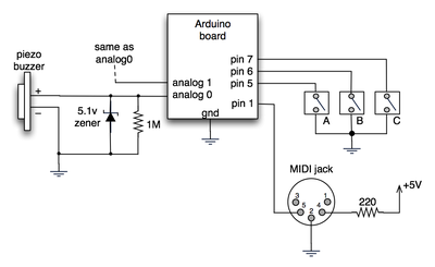
(Note: depending on what kind of MIDI connector you’re usign (jack or cut-off cable), you may need to swap the connections to MIDI pins 4 & 5).

For the piezo input, the 1M resistor is to bleed off the voltage generated by the piezo when it is struck. The 5.1v zener diode is there to insure any large voltages don’t make it into the Arduino and blow it out.

Arduino code

The code has a few tricks that may not be immediately obvious. First is that to implement a MIDI interface, all you really need is the ability to send serial data at 31,250 bps. This is easily done with “Serial.begin(31250)“. Once that is done, a complete three-byte MIDI note-on message can be sent with three “Serial.print(val,BYTE)” commands.

The next tricky bit is that the switches in the above schematic don’t need pull-up resistors. This is because the internal pull-ups in Arduino’s AVR chip are turned on with a “digitalWrite(pin,HIGH)“. This may seem counter-intuitive, doing a digitalWrite() on an input pin, but it’s how the AVR works. The benefit is that you no longer need a resistor to +5V and the effort to wire up each additional button is much lower.

The final trick is measuring impact force on a piezo. When piezo elements are struck, their output voltage rings, sort of like a bell. Kind of like this:
piezo whack!

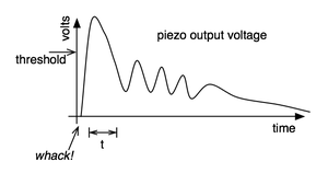
By measuring the time it takes for that first big jolt to cross a threshold, you can get an idea as how big the force was. In the code this is represented by reading the analog value and if it’s over the threshold, wait until it drops down again, counting all the while. When I’ve done this before, I used an input opamp to convert the analog signal to digital (thus doing thresholding in the analog domain) and then used interrupts to get very accurate force measurements.

Arduino code: midi_drum_kit

References

153 Responses to “Spooky Arduino Projects #4 – Musical Arduino”

Wich program do you use to make those electronic diagrams?. I asked this in the last post but I suppose you didn’t read it. I beg you to answer me. Thank you so much.

Hi Coli,
Sorry about that. The program I use is OmniGraffle. It’s pretty much the Mac answer to Visio (except so much nicer looking).

Drawing schematics with OmniGraffle is time consuming though and is only usable for very simple schematics. When I’m drawing schematics “for real”, I use Eagle which is one of the best schematic drawing programs out there (and free for personal use!).

Thank you again! I’ll try both Ommigraffle and Eagle. And congrats for your arduino tutorials =)

Looks gr8!

Can you connect the board to a computer and feed the midi to a sequencer software (Cubase)?

(see also http://createdigitalmusic.com/2006/10/30/diy-midi-drum-triggers-with-arduino-midi-over-usb/)

eric.b: yes, definitely. In fact, in the video, the sampler I’m triggering is Impulse in Ableton Live and the track was recording everything I played.

Nice!
And how did you interfaced with ableton Live?

To interface to Live, I have a MIDI interface for my Mac. There are lots of different ones out there. The particular one I used is also a MIDI keyboard. It’s the Korg microKONTROL.

So Arduino has a midi OUT which connects to the microKontrol midi IN, and the midi OUT of the microKontrol goes into your MAC that runs ableton LIVE?

That’s the conceptual signal flow, yes. The Arduino is plugged into the microKontrol via a MIDI cable and the microKontrol is plugged into the Mac via a USB cable. The microKontrol is a USB-to-MIDI interface (the Mac doesn’t have a MIDI port built in)

[...] Found this whilst trawling through some websites looking for ways to make my sound applet. http://todbot.com/blog/2006/10/29/spooky-arduino-projects-4-and-musical-arduino/ – pretty cool stuff huh!! [...]

Hi,
Is it possible to connect the Arduino directly into a Windows based PC to trigger samples?

Hi lpearce,
It’s definitely possible. There’s a few different ways to go about it, but all hinge on having some program on the PC that listens to a serial port (which is what Arduino’s USB port looks like to the computer) and then triggers samples.

If you use Max/MSP, Pd, or similar algorithmic music composition tools, they already have built into them the ability to listen to serial devices. If you just want to trigger samples, you can use Processing to read the serial port and trigger sounds directly, as shown in the code in the Spooky Arduino Projects notes.

There may even be some serial-to-MIDI driver programs for the PC you could run that would make the Arduino’s serial look like a MIDI port to any PC MIDI program. I wrote a similar program for the Mac and a serial-connected Roomba called RoombaMidi. I don’t know enough about virtual serial ports on the PC to make it work there though.

Hi there, im new to elecronics, but the idea of making drum triggers is superb, could you give me an idiot guide to the components that i need, i want to go to my local maplins and have a crack at it.
thanks for your help

[...] Recently I acquired an Arduino board.  This nifty little gadget is like Lego Mindstorms for grown-ups:  a dirt-cheap microcontroller system you can program from the comfort of your home computer without needing expensive extra hardware.  It’s very hacker-friendly, and folks have used them to make all kinds of nifty things, from a MIDI drum kit to a virtual chainsaw.  I’ve already got all kinds of wacked-out projects in the works (perhaps even my Internet-controlled automatic flush toilet?)  Of course, in order to actually build anything, I need some electronic components, and in times past, when such a need arose, I would gravitate to Radio Shack. [...]

What a great idea, especially with the piezo buzzers!

I was wondering what voltage piezos you used in conjunction with the 5.1v zener diode and 1M resistor and what is the limit of the voltage for the analog inputs on the Arduino is?

Cheers,

Mo

Hi Mo,
The piezos are just whatever I had laying around or the ones at Radio Shack. That is, they’re the most common, cheapest piezos. These piezos can produce voltages into the hundreds of volts depending on how hard you hit them. The actual value of the voltage they produce isn’t important for the applications presented here.

The Arduino inputs, like most all microcontrollers, are limited to between 0V and 5V. If you get above that you may damage the inputs. In reality, all microcontrollers have protection diodes to bleed off voltages that are too above or below that range so you don’t really need the 5.1V zener diode. I like to add it just in case.

Hi, I’m so happy to see this great project!
Should I use a 9v battery instead of 5v usb connection?
It is very picky to control the piezo output voltage.
I’m using it with an analogue multiplexer. :D

Hi Enok,
A 9V battery should work fine. It’ll probably last for around 10 hours of continuous use.

I’m not sure which analog multiplexer works that you’re using. It must have really high input impedance (around 10 Mohms) so you can sense the piezo’s output voltage.

[...] MIDI Output (from ITP physcomp labs) and from Spooky Arduino (21)森  [...]

hi, how would you compare the arduino based with the commercial ones like vdrums or maybe the ones from edrum(also a diy)

Hi Melvin,
Any professional product like the Vdrums will be vastly superior. This is mostly a toy. It’s an afternoon project to play with. I’ve not seen the edrums diy so I don’t know if it’s as much of a toy as the Arduino project above, of it it’s actually designed to be a real MIDI drum brain.

How easy is it to send MIDI out from Arduino to a PC through the standard USB interface? Would Windows-based MIDI software see the Arduino as a MIDI interface if it’s sending MIDI formatted messages over serial?

Hi jbc,
In short, probably not.

The Arduino’s USB interface appears as a virtual serial port to your PC, not a MIDI interface. This means that most music software won’t see the Arduino as a MIDI device. I think there are some programs like Max/MSP that can treat a serial port as a MIDI device but it’s not a standard practice. There might also be a serial-to-MIDI converter program you could run on your PC to create a fake MIDI interface. I’ve done this on the Mac but I’ve no idea how to do it on Windows. If you find such a program, let me know!

cool – what software on the Mac did you use?

jbc,
For Mac OS X, I built a Roomba-to-MIDI driver that appeared as a virtual MIDI interface to standard MIDI software on the Mac. Coding-wise, talking to a Roomba and talking to an Arduino is very similar. I had planned on slightly reworking the code for Arduino but never got around to it.

hi there..
i juz wanna request for a diagram…
can u interface piezo sensor with plastation controller? i try it once for drummania game but it doesnt react that fast… maybe you can help built it from scratch… i am a noob in electronics…
sorry for my bad english
goodluck to you
thanks

Can you Todbot or anybody here tell me how many sensors or piezos this project will take? I see five in the video. Can it take 8 without serious modifications? And Todbot, why do you think this is just a toy? A simple velocity sensitive, battery powered trigger-to-midi converter is a great tool! I was thinking about trying this.

Hi frog,

The Arduino has 6 analog input pins, so you can have 6 piezo pads. The Arduino also has 14 digital input/output pins (one of which must be used for MIDI out), so you can have at most 13 buttons.

I consider it a toy because I whipped it up in an afternoon. Also, the piezo velocity-sensitivity measurement as implemented isn’t very accurate. To get it more accurate would require some input buffers added to the hardware and better access to interrupts.

But yes, you can pretty easily make a portable battery powered 19-input trigger-to-MIDI out of an Arduino and it would work reliably and be a lot of fun.

Dang, fast reply! So 6 is nice. Um, just how inaccurate is it?

(heh. I get email when someone makes a comment)
I didn’t quantify the lack of accuracy, except to note that it was far rougher than a similar system I built in ‘90. :)

I’m sure if you played around with the code you could make it more accurate. Poke around on the Arduino site & forums to see if anyone else is working on trigger-to-MIDI code. Chances are someone is and they probably have a more elegant solution than my quick hack.

Hi and congratulation,
You were speaking about sending midi through the USB flow… and thank you for the link toward the MAC convertor ;)
But i m wondering if there is not a problem of bandrate …. it s not 9600 in midi message, but is the convertor will understand it ?

Hi,
The converter program I mentioned above doesn’t care about the baud rate (which you’re right, MIDI is at 31250 bps and most Arduino sketches are at 9600), because it’s just receiving data from one part of the computer’s OS and sending it to another. The baud rate difference would only be a problem if you’re trying to send a lot of MIDI (or very accurately-timed MIDI) over your 9600 baud link.

Hey,
I was wondering if this board would support enough triggers to make a midi xylophone. (probably around 60) If not what would be an alternate solution?

Hey Tod, thanks so much for this tutorial. I was wondering though: you say in the PDF “there are much faster ways of watching inputs than loops with analogRead().” What are those faster ways? Can it be done on the Arduino?

Hi Tyler,

The two common ways of quickly and reliably reading analog inputs on microcontrollers is 1) have a periodic timer interrupt that reads the input, or 2) have an interrupt that is triggered when the analog-to-digital converter completes its conversion. When an interrupt fires, it runs a bit of code that’s separate from your normal main loop. Recent versions of Arduino provide easy access to some types of interrupts, but I’ve not played with them much yet. Also, the Arduino IDE doesn’t stop you from using normal AVR C code to do your own interrupts (though you do have to be knowledgeable about how the Arduino code sets up the AVR chip on the Arduino board)

thanks a lot for this page, tod. i think i found one error in your schematic. pins 4 & 5 on the midi connector seem to be swapped. in making this simpler version of what you’ve got as a test of my Nintendo game pad library, i noticed that everything seemed to be working but my midi-usb interface wasn’t getting the messages. i found another pinout with those pins swapped and it worked correctly after that. thanks again and good luck.

hi tod,

i noticed that your noteOn() and noteOff() are the same. on this page, it looks like your (0×80 | (channel

Sorry, you can ignore that last comment – I should’ve kept reading down below where it says that a noteon with a velocity of 0 is the same as a noteoff. I’ll stop now. Sorry again, but I’m on a roll right now. Thanks for the insipiration.

Hi Rob,

About the MIDI jack and pins 4 & 5: it depends on whether or not you’re talking about a MIDI cable or a MIDI jack. I was following what other Arduino users have done as discussed here and here and I think perhaps we may’ve all be using a cut off MIDI cable instead of a proper MIDI jack.

As for noteOn() and noteOff(), yeah it’s a hack, and a hold-over from when I first started doing MIDI programming back in the ’90s. Some MIDI devices didn’t respond correctly to the “note off” command but did to “note on with zero velocity”. It makes for confusing code and I should change it (or at least document it).

Good luck, and when you do a blog post about your creation, please link to it here in the comments, or post something about it in the Arduino forums. Others can learn from the additions/advances you make.

Thanks again for the info, Tod. Here are the links:

The NES joystick library for Arduino
An NES joystick MIDI controller
Another MIDI controller made from a kid’s toy

Fun stuff. Thanks again!
Rob

Any idea where to get the MIDI Jack from online? I tried a few google searches, but no luck, nor from the component sites listed here. Thanks in advance!

Hi Ben,
If you’re looking for a “midi jack” on Jameco or Digikey, you probably won’t find it. The real name is something obscure like “5-pin 180º DIN jack receptacle with female sockets”. The cheapest/easiest might be just to get a “PC/AT keyboard extender cable” or even just a MIDI cable and cut them in two. I’ve done that several times.

If you want a proper jack you can solder to, here’s one from Jameco.

Tod, thanks so so much for the tutorial (and all the stuff on your site).

You won’t believe how frustrated I’ve been tonight. I went over my connections a trillion times, but could not understand why I wasn’t getting any midi out from my Arduino……until I read Rob’s post about swapping pins 4 and 5 – which I did, and now everything is working perfect.

Thanks again, and thanks Rob! :)

I’ll send you info on my project when I’m done.

Oh, and btw: the NYU Computer Store sells the “midi jacks” as “5 pin DIN connectors” for $1.45.

Ben: just remember to swap pins 4 and 5…

Hi, great post. I wrote a Mac OS X application that creates a virtual MIDI instrument from Arduino serial output. This eliminates the need for the MIDI module as you described. I made an electronic drum kit out of it. See: http://code.google.com/p/ardrumo/ for details.

Thanks a lot for the tutorials. This opensource is indeed exiting and revolutionary.

Anyways, I’m new to microcontrollers and arduino, (have a little coding experience though)

You mention input buffers for better control of the piezos. I found some information about loading down the piezos with several 10Meg resisters and then buffering the output voltage with an op amp such as the U1-A.

I was wondering if this would work, and, if it would help anyone, to link to the information…

http://www.musicfromouterspace.com/analogsynth/SOUNDLABMINISYNTH/drum_trigger.html

Hi there,
Thanks for your info!
I’m building a led-system into my drumkit and your trigger-diagram helped me to generate a nice input for my microprocessor. About your analog inputs, you can link buttons parallel with several different resistors and use just one analog input to read which button is pressed. By using for instance 1k, 2k, 4k, and 8k, you can read exactly what buttons are pressed using just one input.

byebye

I may be wrong but there is something in your .pde code which is funny:

You use
midiMsg( (0×80 | (channel<<4)), note, velocity);
for noteOn and noteOff messages.

In fact, it should be 0×80 for noteOff, and 0×90 for noteOn.
And, instead of (channel<<4), you should use (channel-1).

Interestingly, your code works because as you are only using channel 1, 0×80 | (channel<<4)) gives 0×90 (which is the code for noteOn).
And so for noteOff, you send a noteOn with a velocity of 0 (which is interpreted as a noteOff by all synths, but is not exactly the same thing… as it is possible in MIDI to have a noteOff velocity).

Hi Patrick,
You are entirely correct. As I mention in the comments above, the “noteOff as noteOn with zero velocity” is not a bug but a purposeful lazy hack that I’ve been doing for a long time and should probably stop now that I’ve received multiple comments on it. :)

very good stuff todbot.
comments of other users (willem & mschaff) are very interesting, it gave me new idea to clone the monome with velocity pads (!).
yes, u have to improve your midi langage, this will give you more possibilities.

Excellent stuff ! managed to adapt it to take 5 peizos and finally got it working ( as i have no previous programming experience). However i noticed when monitoring the incomind midi signal that there are often more note off messages than note on,and i cant figure this out, this was also the case before i expanded the code to include 5 piezos. Do you know why this happens and if it can be sorted ?

Hi Daniels,
I’ve not seen your code, so I can’t tell you for sure, but I bet it’s a misplaced curly-brace for the initial “if()” statement.

[...] MIDI OUT: read a piezo and send midi notes tutorial [...]

[...] DIY Arduino MIDI Drum Kit [link] [...]

http://code.google.com/p/s2midi/ or here http://www.memeteam.net/ has a serial to midi translator app for windows just fyi, no reply required

hey man, great tutorial, I was wonderng if you had any insite into how to do the oposite, taking midi data (a midi file) and getting it to control some external device (using the Arduino)

I’m working on a similar setup but using a pic 16f690 instead. I found a PC serial midi driver that works great so far:
http://www.roland.com/products/en/_support/dld.cfm?iCncd=724&ln=en&SearchBy=RcId&dst=P&iRcId=0000010777&dsp=1
The only trick is that you should set the serial port speed to 38400 instead of the midi spec speed of 31250. Apparently due to integer boundary timing :) Either way, I hooked up using the standard serial port and the few midi monitor program I tried saw the driver and got the midi messages exactly as sent.

Thanks for the nice video and project todbot!

Thanks to mschaff for good details on constructing cheap pads.

My question is how many levels of velocity can this code/hardware accurately measure? Talking with an audio buddy, he didn’t think software would have more than 3-7 velocity levels for any given drum channel. If this simple hardware can achieve that then I’d be more than satisfied since I prefer simple hardware (being a software person) and am not a drummer.

Hey again. :) I’m starting to make some great progress on trying this out. I built a full kick pedal with the sensor integrated…

check it out: http://somesoundswelike.com

I’m running into the double or triple triggering problem… I have a few ideas about how to defeat it, but if you have any insights, I’m all ears.

thanks as always! your content is freakin’ awesome, and stays awesome for a long time. :)
-steve

great tutorial. I am trying to do the same thing for learning purpose. I’m a programmer but I don’t know anything about electronic.
I stopped by radioshack last night and they have so many different piezos that I didn’t know which ones to buy. Is there a ref number on the one you stripped down?

I was also looking into the labjack U3 from http://www.labjack.com/labjack_u3.php?prodId=25

Do you think this would work?

Thanks for your time
-David

Hi David,
That LabJack you mention is mostly for data collection in labs, I’m not sure how well it would work in a real-time environment. That is, it contains no intelligence, just inputs & outputs. The Arduino contains a small computer that can act on its inputs and twiddle its outputs

As for which piezos, generally the rule is “get the cheapest”. You want to get “piezo elements” and not “piezo buzzers”. The latter contain driver circuitry to make noise. I believe the piezo elements from Radio Shack I’ve had success with is 273-073.

fantastic tutorial :] just wondering if there is a way to add on additional analog inputs? could they perhaps piggyback/cascade from one to another board?
thanks again for sharing your info..
Cheers
-Jake

Hi Jake,
There are analog multiplexers that let you switch many analog inputs to one. (pick which input to read, read it, pick next input, read it, etc.) This doesn’t truly expand the number of inputs you have, but you usually don’t need to truly read each input simultaneously.

There are also many I2C analog-to-digital (A/D) converter chips out there that are pretty cheap.

It works!!
I started to program this MIDI interface a long time ago, and I had problems reading the piezo when played fast (some notes were missing), and then I found your little “hack” that saved my life!
Well, the only problem I’m having right now is that there seems to be a little lag in the analog-to-digital conversion (very annoying), long enough to make it unplayable (switches don’s have lag).
In the video I see you don’t have any lag at all, and I wonder if my problem is due to my version of the Arduino board: Arduino NG rev.c

Any ideas?

Thanks!
Bran

Hi Bran,
The lag is likely not due to the A/D or the version of Arduino you have (I originally did this on an NG I think)

More likely (if you’re using my code above), it’s the part of the code that attempts to determine “velocity” of the hit on the piezo. Instead what you might want to try is just measure any hit at all. (like in the KnockSensor Tutorial)

If you don’t get any lag with that, it’s definitely an issue with the velocity-determining code (which is a real hack on my part). If it’s not that, be sure you have that 1M resistor across the piezo. That’s needed or the piezo just builds up a charge on it and you can’t measure anything useful, but could perhaps show up as a sort of ‘lag’.

(and congratulations on it working! :)

Hi, I’ve tried the simple way, and I get almost the same lag:

val = analogRead(piezo);
if (val > threshold)
{ noteOn(0×90,note,val/8);
delay(1);
noteOn(0×80,note,0×00); }

With this code I also get double notes on one stroke, so I tried this other way:

val = analogRead(piezo);
if (val > threshold)
{ if (already_playing==0)
{ noteOn(0×90,note,val/8);
already_playing=1; }
} else
{ if (already_playing==1)
{ noteOn(0×80,note,0×00);
already_playing=0;}
}
delay(1);

This eliminates most of the double notes, but the annoying lag is still there… :(

I’m mostly on the side that it has to do with my board and the analog inputs, because the digital inputs have no lag at all.

Anyone here with the same board (Arduino NG) have succeeded with no lag?

Thanks,
Bran

Great project todbot,
In relation to those who were inquiring about more inputs, I am wondering if this might be possible using triggers set up in a matrix fashion similar to the way keyboards work. I know this wont be possible with the piezos but do you know if might work with switches on the digital inputs ?

[k]

Hi keet,
That’s a really interesting idea, having the piezos in a matrix. My first instinct is that it’s not possible, because the piezo signal is analog (not digital) or because the loading of the other elements would make it hard to read just one.
But some more thought and some experiments would be warranted to say for sure.

Greetings todbot!
I recently got an Arduino and have used your projects quite a bit already. So first off, thanks! Very useful stuff.

I’m having an issue with one of my fiddling projects though and I think this particular project may help me fix my issue. So, here’s my questions for you:

In the following code;

noteOn(1,note_crash, t*2);
delay(t);
noteOff(1,note_crash,0);

What happens if you punch one of the buttons, or hit the high-hat, _during the delay_ between noteOn and noteOff? Does that instrument play as well? Overlapped with the current instrument, right after the current one finishes, not at all?

I watched the video a couple times, but just can’t quite figure it out that way. I also don’t have any midi anything around here to just try building the thing myself.

Thanks in advance,
Del

Hi Del,
You’re very perceptive. If you hit a button or piezo during the delay(), it won’t be read. I probably shouldn’t have done the delay like that. If you want, you should be able to make the delay small and constant (e.g. “delay(10)”). If you’ve set your MIDI device to “drum” or “trigger” mode then it shouldn’t matter how long the note is held for. But you should still send a note off to avoid the stuck-note issue of some MIDI modules.

Thanks for the answer!
This is exactly the problem I’m having with a different project. While being completely new to this microcontroller thing, I’m trying to figure out how to make the Arduino recognize/respond to button input during the (heavily delayed) loop. The buttons are speed up/down and mode left/right, changing the speed and sequence of a wad of LEDs (my newbie learning project).

Fun stuff, I’m used to writing PHP, and have never had to deal with concurrent events in my code. Kind of a waker-upper to not have a threading daemon backing things up :)

Yeah it’s tough with microcontrollers because you can’t spawn a new thread or process to take care of stuff.

There are two ways to go about it. One way is to use interrupts. This is where you associate some external event with a chunk of code. Arduino supports a type of interrupt, so that might work for you.

The other way is to remove all delay()s from your code and instead use millis() or many shorter delays() to check if enough time has passed. For instance, instead of doing this:

  doFirstThing();
  delay(1000);     // wait for a second
  checkButtons();  // but now it's too late
  doSecondThing();

you can instead do something like this:

  doFirstThing();
  for( int t=0; t<1000; t++ ) {
    delay(1);       // wait just a little bit
    checkButtons(); // button resp. fast now!
  }
  doSecondThing();

or something like this:

  doFirstThing();
  int starttime = millis();
  while( (millis() - starttime) < 1000 ) {
    checkButtons();
  }
  doSecondThing();

Or better still, leave out the while altogether and check for needing to do an action each time through loop(). E.g. something like:

boolean thingHappening = false;
int startTime;

loop() {
if (someCondition) {
doFirstThing();
startTime = millis();
thingHappening = true;
}

if (thingHappening && ((millis() – startTime) >= 1000)) {
doSecondThing();
thingHappening = false;
}
}

The advantage of a “state machine” scheme like this is that you can have more than one thing happening at the same time.

I’m not sure about this but I think the Arduino code can lose characters received on the serial port during calls to delay() which are too long. delay() is convenient for quick experiments but I think it’s usually better avoided the moment you want to do anything a little bit complex.

In the previous post I should really have said explicitly that the idea is that you can have a call to checkButtons() or whatever in each pass through loop().

I’ve been banging my head against the wall on the piezo double/triple trigger problem… still. :) I used tom igoe’s sensor reading and charting technique and have something resembling actual science now.

please come take a look and leave a comment…
http://www.somesoundswelike.com/2008/02/02/diy-drum-triggers-reading-the-sensor-scientifically/

I’m thinking about the multi-sensor problem, too. Although, i think you could limit it to 4 concurrent sensor readings, since you typically only have 4 appendages that you can hit sensors with at any given moment… I dunno if that really helps the problem or not, but it’s something I’ve been thinking of.

Hello guys..
well.. Super! i’m looking for arduino exactly as a midi interface..but i want to use this with Live ableton…
Can u connect that ddirectly to live ableton?? without the minikorg?

Hi! You don’t need the minikorg. But you will need a hardware MIDI interface for your computer (~$40). Or you could run a converter program to convert the Arduino’s USB serial messages to internal MIDI messages. A few of these converter programs are mentioned above. Also, poke around the Arduino forums and you’ll find others.

[...] Spooky Arduino Projects #4 – MIDI Drum Triggers [...]

[...] 1 – Code and software Link 2 – Video and wiring » Filed under Interaction Design by Mikko at 17:52. back to [...]

so i managed to get an RBBB assembled (really bare bones board – check out http://moderndevice.com ) and working last night to the extent of sending midi out to a korg esx-1, just playing scales over several octaves… so challenge met halfway…

i’ve been reading the posts here and regarding the multiple ’strikes’ issue – i have to wonder if the key isn’t simply adding, as tod suggested in the original diagram – the diode and resistor to the signal path of each piezo… i’d be very interested in graphs showing the ringing effect with and without several grades of diode and resistor values.

also, what’s the response time of a power regulator ic? perhaps that may be used, or used in conjunction with a diode and/or resistor, to normalize the impacts even more… so that you don’t have issues associated with some strikes going so beyond your target threshold that even some of the rings qualify as additional hits as well.

and taking the analysis of the problem a step further… one could also investigate the properties of envelope generators of analogue drum machines which are particularly good at very sharp decay… you could apply an EG to each piezo and then you really would just be seeing one significant peak to be compared to your threshold.

You got it, Kris. The real trigger-to-MIDI converters have a per-input op-amp input state to condition the piezo input, very much like an envelope generator. Though I think their op-amp circuits are more like comparators that convert the piezo input to a on/off signal, where the ‘on’ duration indicates the velocity of the input strike.

I’ve made a drum-trigger with arduino, based on your project among others, and i solved some issues (as double/triple trigger on a note) just by using a peak-detector. Results are smoother than using a single piezo. A simple peak-detector is made with a diode, a capacitor and a dicharge resistor. I found some interesting info about this topic at Paia’s web:

http://www.paia.com/ProdArticles/drumsens.htm

This works by charging and discharging a capacitor (and using an op-amp after), so i think it’s not by “on” duration, but by the charge level of the capacitor when being discharged, so you can measure variable voltage on output. You can use a pot too, and then you can increase and decrease the threshold (sensivity) for a drumpad.

Keep rocking!

i had also recurring thoughts of ‘capacitor’… what if: you added a capacitor after the diode and resistor (both to bleed off more severe strikes), then, follow this algorithm, in your loop() — 1. take a reading of the voltage coming off the capacitor — 2. if it meets your ‘attack’ voltage, set a counter to zero — 3. while the voltage is greater than a ‘decay’ voltage, increment your counter and delay (by 1ms?) — 3a. if your counter is greater than some max value, break out of the while loop — 4. once out of the while loop, evaluate your counter versus the initial ‘attack’ voltage reading… the two together should give you some indication of how hard the piezo was struck as well as how long it took the capacitor to discharge i.e. how much energy was stored into it as a result of the strike velocity, and thus, you’ve got one velocity reading… obviously this adds some latency into evaluating each strike but depending on the type of capacitor used the discharge could happen very rapidly.

mm, just realized a required slight modification to the above algo — while in the while loop waiting for a ‘decay’ voltage, add an if statement to update the ‘attack’ voltage if you get a reading higher than the initial ‘attack’; this will account for cases where the ringing of the piezo is slightly delayed.

Hi Kris & Fabi, Yup, that algorithm you mention Kris is basically the one implemented in the original Arduino sketch above. The general term is “thresholding” or “comparator”. I found in my experiments that measuring the signal via thresholding was more reliable that measuring peak voltage for piezo signals.

That PAIA page linked by fabi is great and very instructive. It contains two very useful sub-circuits: a peak detector and a voltage buffer. In the Arduino circuit above, I was hoping the intrinsic capacitance and built-in diodes of the AVR’s input pins would be enough to act as peak detector. And that the high-impedence of the pins would not require the use of an op-amp buffer.

I think I used that very PAIA info when I built my senior EE project: “perc-a-lator”, a trigger-to-MIDI converter, back in 1992. (schematic here) I omitted the op-amp buffer that’s in the PAIA circuit because the microcontroller I used also had high input impedance and a fast A/D.

i intend to set up a few experiments this weekend, graph and compare what i get out of a zener versus a 200v peak inverse rectifier (in4003), both going to a 1mohm resistor and finally a capacitor… (i’ve got a theory about using a rectifier instead of a zener.)

have no idea what capacitor will work best… though i think i like the sound of ‘2.2µF 50V 20% Nonpolarized Electrolytic Capacitor 9,000Hz’.

as for the envelope detection/correction i’ll stick with doing it in my sketch and modify the heck out of a state machine to manage all 6 inputs.

i’ll post my findings when i’ve got ‘em! :)

so here’s my current arduino sketch to test trigger values/enveloping on all six analogue inputs in a state machine with no inner loops (other than the one to traverse all six inputs)…


int led = 13;

int env[] = {128,384,256};

byte s[6];
int i[6];
int v[6];
int t[6];
int x = 0;

void blink(boolean b)
{ digitalWrite(led,b ? HIGH : LOW);
}

void setup()
{ pinMode(led,OUTPUT);
  for(x = 0; x < 6; x++)
  { s[x] = 0;
    i[x] = 0;
    v[x] = 0;
    t[x] = 0;
  }
  Serial.begin(57600);
  Serial.println("----");
}

void loop()
{ for(x = 0; x  env[0])
      { s[x] = 1;
        t[x] = 0;
        blink(true);
      }
    }
    if(s[x] == 1)
    { i[x] = analogRead(x);
      if(i[x] > env[1])
      { s[x] = 2;
      }
      t[x]++;
    }
    if(s[x] == 2)
    { blink(true);
      Serial.print(x);
      Serial.print(";");
      Serial.print(i[x]);
      Serial.print(";");
      Serial.println(t[x]);
      i[x] = analogRead(x);
      v[x] = max(v[x],i[x]);
      t[x]++;
    }
    if(i[x] < env[2])
    { s[x] = 0;
      blink(false);
    }
    delayMicroseconds(1);
  }
}

Is there a midi module that i can use that is at a reasonable price range? roughly no more than $200 or less?

Hi Mike, yes, there are many MIDI adapters for your computer. Usually around $40 or so. For instance, there’s the M-Audio Uno that I’ve heard works well.

[...] zum Beispiel eine eigene LASER HARP nach dem Vorbild Jean Michelle Jarres zu bauen oder ein eigenes Trigger-Drumkit entwickeln. Die Möglichkeiten sind schier endlos, da jegliche Art von Sensoren und Aktoren [...]

[...] zum Beispiel eine eigene LASER HARP nach dem Vorbild Jean Michelle Jarres zu bauen oder ein eigenes Trigger-Drumkit entwickeln. Die Möglichkeiten sind schier endlos, da jegliche Art von Sensoren und Aktoren [...]

I’m currently building a midi controller to interact with ableton live and your project has helped a lot. I’ve got several pots all hooked up and working but I’m having problems with the coding for the buttons to trigger the clips in live. Have you done anything similar? Do you have any examples that might help?

Thank you in advanced.

Mark

Hi Mark,

Do you have the buttons hooked up exactly like the schematic I have above? I did a bit of trickiness with the buttons that is easy to miss. When hooking up buttons, you normally need a “pull-up” or “pull-down” resistor. See the Arduino Button tutorial for an example with a pull-up resistor. If you have some 1k to 10k resistors, try hooking them up as in that tutorial and see if that solves your problem.

The trickiness I did was to use the internal pull-up resistors that are part of the chip in Arduino. That’s what the:
digitalWrite(switchAPin, HIGH); // turn on internal pullup
line does and you need one per switch.

The other thing to realize is that when the switches are hooked up like this, they produce a LOW when pressed.

[...] Algumas inspira??es para este projeto: Ardrumo Spooky Arduino Projects #4 – Musical Arduino [...]

Hi Tod,
thanks for the advice about using a MUX to “increase” the analogue inputs on the Arduino. I’d like to interface with MaxMsp but am struggling with the code. The piezo seems to trigger all the inputs on Arduino out of the MUX. Is there anyone who could offer advise on the code. Also, is there any schematics for interfacing an ADC to also increase piezo inputs by utilising the digital i/p on the Arduino.
Thanks

[...] 19-input trigger-to-MIDI out of an arduino and it would work reliably and be a lot of fun. …http://todbot.com/blog/2006/10/29/spooky-arduino-projects-4-and-musical-arduino/BlockoS ? arduinoAs I managed to make the arduino software work under linux, I did this week Make [...]

Hi!
This is really what I’ve been looking for. An easy MIDI-drum. My question is: do I need that green “Proto-Shield” or can I make it with just a “Arduino Diecimila USB board”? I have never seen the Arduino board before..
thanks!
- Mattias

Hi Mattias,
You don’t need a shield, but you’ll find that having a solderless breadboard to be a very useful add-on to an Arduino board, for this project and in general. If you’re looking for a really simple and inexpensive solution, take a look at this 1¢ under-shield idea. :)

Hey there,

I had found your site back in February, and had decided at that time to make a real, professional grade EDrum set using the Arduino. The initial prototypes were closely based on our work, but it evolved past that. If you (or anyone else reading this) are interested, you can check out the website http://drummaster.thecave.homeunix.org.

While my design is not MIDI based, it is generic enough that you should be able to substitute the MIDI code and instructions found here, and replace my custom serial protocol to make a true MIDI drum set. (The reason I chose not to use MIDI is that my own protocol, along with the slave software running on the computer, is much more customizable and (IMHO) powerful than a MIDI based solution would be.)

Drum Master, with the associated Drum Slave software, allows up to 32 analog (velocity sensitive) inputs and 8 digital switches, has ports for 16 drum pads, allows up to 6 zones for each pad (by using RJ45 ports, you can get GND, V+ (for active electronics such as accelerometers / LED sensors), plus 6 data channels), etc. Full schematics, PCB layouts, software, images, movies, etc are on the site. Everything is licensed under a CC license.

I have a couple of shields left over from the PCB run, if anyone is interested in the ‘official’ version; you can contact me for details.

Cheers

Hi Wyatt,
Very nice. And awesome project writeup. I’ve had many people ask if the Arduino could be made into a good electronic drum brain and while I’ve said it could be done, I’ve not (until now) had a good example to point them at showing that it could be done well.

wyatt — Seriously thorough!

[...] I hooked up four piezo sensors to my Arduino board and got some help from Tod E. Kurt’s tutorial on handling piezo [...]

[...] doch lieber einfach? Im TodBlog steht, wie man einfach mit einem Arduino Midi-Messages verschicken kann. Da würde das ganze Protokollgebastel wegfallen. Und wenn das Senden so einfach ist, wie [...]

This is a really cool project. However, there s some questions,I need to ask before I make it.

I can se that you’re using an older Arduino version. would the code provided on this page work with the Diecimila?

Will it work with a really cheap midi interface like the one, I found here:
http://search.stores.ebay.com/Daily-Neccessaries_midi_W0QQfciZQ2d1QQfclZ3QQfsnZDailyQ20NeccessariesQQfsooZ1QQfsopZ1QQsaselZ429237349QQsofpZ0

Hi Christian,
Yup, this code will work with kind of Arduino. And any MIDI interface should work, the cheaper the better in my opinion. :)

[...] the schematic of this project channel 1: adding a diode to avoid negative volts channel 2: without a diode (like the original [...]

Hi,
I’m trying to setup the spooky sound trigger you describe in your notes using Processing sketch you wrote. I keep getting an error that says unable to load spooky00.wav … It reads the serial fine from the piezo and draws the eyes, just no sounds. Any ideas? Is there a special place I need to put the .wav files? (I’ve tried everywhere I can think it would be looking for them). Thanks!

Hi David,
Yes, you create a “data” directory in the same directory as the .pde file for Processing, and then stick whatever sounds you want in there. For example, see the Processing sketch directory here:
http://todbot.com/processing/arduino_spookysounds/
and how there’a “data” directory filled with .WAV sounds.

Thanks Tod,
I created the data directory with the .wav files and it still gave me errors. I did have this working last year, only thing that changed was that I now have a new PC with vista. So I tried setting it up on my laptop that is running XP, and it works fine. So I guess there is some issue with processing and vista?

Oh that’s pretty weird. I wouldn’t have expected that. I don’t use Vista so I’m not much help. Are you running the latest version of Processing?

Yea, Processing 0154.

How is the Arduino able to output to the computer? Does it bypass the MIDI module and go straight to the computer? Or is it routed through the MIDI module? I guess I’m confused as to how a sampler on the PC would recognize the input… Can someone please clarify as to how this is done? Is it possible to output the MIDI data to PC directly and have the PC recognize and play the sounds?

Hi Mike,
The Arduino is configured to be a MIDI controller. It outputs MIDI over a MIDI jack. So you can hook it up to anything that has a MIDI input.

In order to hook it up to your computer, you have to do the somewhat non-intuitive thing of hooking it up through a MIDI interface (I have an old 2-port USB-to-MIDI that I used in the video)

There are efforts to turn write OS-specific drivers to turn the USB serial interface built into Arduino into a kind of MIDI interface, but the point of the sketch above was to show how to generate regular MIDI.

Hello!

This is cool! Thanks! :) I was thinking to make this kind of project to control MIDI things in FL Studio and other(s) music DAWs. 6 piezos should be enough, but now I can’t figure out how many and what components, I need to do this(“that”): 6 piezos I think is OK but resistors?6x? 1MOhms for each? zeners?

Any help? Thanks :)

Hi! For each input, you have a piezo, a 1M resistor, and a zener diode. (many people leave off the zener, it’s a preventative measure)

I’m confused about your answer above regarding sending the data to a pc:
“There’s a few different ways to go about it, but all hinge on having some program on the PC that listens to a serial port (which is what Arduino’s USB port looks like to the computer) and then triggers samples.”

What if you plug directly into a computer MIDI/Game Port?

Hi Ace,
Yup, you can wire up an Arduino with a MIDI out jack and run a MIDI cable between the Arduino and your PC. That works fine. The question I was answering (poorly) was using sending MIDI data over the Arduino’s USB port. For that you need a program on the PC that reads data off the “serial port” that Arduino’s USB looks like to the PC.

Can you explain what the difference is in the SPI vs. Serial (SCI?) interfaces?
I notice that the Arduino info says “These pins support SPI communication, which, although provided by the underlying hardware, is not currently included in the Arduino language.”
I’m actually planning on trying your example using a Motorola processor I already have, and am not sure if I should use the SPI or SCI (RS-232) pins…because I don’t understand the difference, and can’t find anything to explain it to me. It looks like your Arduino example uses what would be the equivalent of my SCI (rs-232), but I’m not sure.

Hi Ace,
Traditional asynchronous serial (what you’re calling SCI above), has two signal lines: TX and RX. One lets a device send data to another device, the other lets a device receive data. Both devices must have a previously agreed upon baud rate (the rate at which data is transmitted) and accurate internal clocks to ensure the baud rates don’t drift over time. If you’ve ever had to hook up a serial device or modem to a PC, you’ve run into the problem of baud rates not matching.

To get around this problem, you can add another signal line to the mix, which is the clock line. Now there’s three lines: Clock, TX, and RX. Every time the clock line wiggles, both sides can send or receive data. This is called synchronous serial communication, because the clock is sent along with the data. This is what SPI is. Normally, in SPI the signals are named SCLK, MOSI, and MISO. In SPI, one device is called the Master and the other is the Slave. The master creates the SCLK signal. Then, data is transmitted out from the master on the MOSI line (MOSI==”master out, slave in”). Similarly, data is received into the master from the slave on the MISO line (“master in, slave out”).

As to which to use for a particular application, it depends. SPI allows multiple slaves, so you can have many devices communicating back to the master. Normal async serial doesn’t allow for this. But async serial is usually much easier to use when it’s just two devices talking to each other. And lots of things speak it. You can get a USB-to-serial adpater much easier than you can get a USB-to-SPI adapter, for instance.

Oh and MIDI is just a kind of asynchronous serial. The main difference is that its baud rate is set to 31250 bps.

Thanks that makes sense.
One last question….it looks like my asynchronous serial communication interface outputs have RS-232 transceivers, so from what I understand, that is not using TTL voltage levels. Will it be a problem if I use these outputs plugged into my midi/game port, or is it only a problem going the other way (TTL tx to RS232)?

Yeah, don’t hook up anything TTL to anything that’s at RS-232 voltage levels. Those are +12V and -12V, guaranteed to fry something. Also, RS-232 logic levels are inverted from what TTL normally is (i.e. in RS-2323 -12V is a “one” and +12V is a “zero”; in TTL, 0V is a “zero” and +5V is a “one”)

I expect your microcontroller can output TTL level serial too.

Hi,

To place a 10M resistor instead the zener/1m would be able achieve the same goal of protection ?

thanks

Seb

Hi Seb, Not really. The Zener diode and resistor are doing two different things. A piezo looks sort of like a capacitor (where the charge on it is proportional to how hard it was hit), so it needs a resistor to drain off the charge built up in the piezo. The trade off is if the resistor’s value is too high, the charge in the piezo goes to the max and you can’t sense anything, but if the resistance is too small, the charge drains away before you can measure it.

The Zener is what blocks the huge voltage that can potentially be produced by the piezo. In practice people often omit the Zener because the Arduino’s chip has a measure of built-in protection.

hey just wondering what range of voltage is produced by those piezo pads, just the initial pulse?

Hi Mark,
The output voltage can be very high, into the thousands of volts, both positive and negative. It’s the same material used to create electrical spark in oven starters and some lighters. The current is very low though, only a few micro-amps, and the duration is very small.

Hi Tod,

First of all, thanks a lot for this great tutorial! I’ve managed to make a multi drum pad out of it and it plays very well.

I used Roland serial-to-midi driver (Windows XP) and for some strange reason I could receive midi messages in my DAW through Arduino’s USB connection (baud rate 38400) without updating the FTDI drivers to midi’s speed of 31250 (I did change them eventually though). Do you have an idea of why it worked?

Also, it seems that I can only get 1 midi message at a time: for example, hitting 2 pads at the same time results only in 1 of them sounding. Is it a problem with the code (“delay” function?) or the Arduino’s internal limitation?

Thanks in advance.

Hi Andrej,
Yup, it’s almost assuredly because of that delay, but not an Arduino limitation. It’s my code’s limitation. :) The code currently waits for a signal on any input, and when it sees one, it spins with a delay loop until the signal drops. While it’s doing that, it’s not reading any other inputs.

Better could would do the same thing but not spin waiting for the signal to drop. Instead it would remember the fact that a signal happened, and keep inputs.

Hi Tod,

I’m having a strange problem with my Roland XV-2020 MIDI module. I know it’s getting the MIDI messages because the MIDI light is lighting up on the module, but it isn’t playing anything. Also, the module sort of freezes – it won’t allow me to go to another drumset or anything. Any ideas on what this could mean? Thanks!

Hi Toni,
Hmm, that is weird. Have you used another device that generates MIDI with the module?

Now that I look at my sketch, I’m pretty sure I had the MIDI code for noteOn() and noteOff() wrong. I had this:

void noteOn(byte channel, byte note, byte velocity) {
  midiMsg( (0x80 | (channel< <4)), note, velocity);
}
void noteOff(byte channel, byte note, byte velocity) {
  midiMsg( (0x80 | (channel<<4)), note, velocity);
}

and it should be:

// channel ranges from 0-15
void noteOn(byte channel, byte note, byte velocity) {
  midiMsg( (0x90 | channel), note, velocity);
}
void noteOff(byte channel, byte note, byte velocity) {
  midiMsg( (0x80 | channel), note, velocity);
}

I can’t believe I had this wrong. I’ve updated the sketch to have this change.

yes, the module works with my keyboard controller. i tried this simpler sketch to see if i can get anything going with no luck:

// Variables:
char note = 0;            // The MIDI note value to be played

void setup() {
  //  Set MIDI baud rate:
  Serial.begin(31250);
}

void loop() {
  // play notes from F#-0 (30) to F#-5 (90):
  for (note = 30; note < 90; note ++) {
    //Note on channel 1 (0x90), some note value (note), middle velocity (0x45):
    noteOn(0x90, note, 0x45);
    delay(100);
    //Note on channel 1 (0x90), some note value (note), silent velocity (0x00):
    noteOn(0x90, note, 0x00);
    delay(100);
  }
}

//  plays a MIDI note.  Doesn't check to see that
//  cmd is greater than 127, or that data values are  less than 127:
void noteOn(char cmd, char data1, char data2) {
  Serial.print(cmd, BYTE);
  Serial.print(data1, BYTE);
  Serial.print(data2, BYTE);
}

there’s something about the MIDI message that it doesn’t like. it must be something weird with that module, no one else seems to have that problem. everything works good with ardrumo, but i’d rather use the module. oh well, thanks anyways.

Hmmm, your simpler example does note-offs with a note-on message with zero velocity (a common technique). Did you you try sending a note-off message instead? i.e. using your code:

{
  ...
  noteOn(0×90, note, 0×45);
  delay(100);
  noteOn(0×80, note, 0×45);
  delay(100);
}

void noteOn(char cmd, char data1, char data2) {
  Serial.print(cmd, BYTE);
  Serial.print(data1, BYTE);
  Serial.print(data2, BYTE);
}

yeah, still not working :\

Can you explain what (0×90 | channel) is doing? The fact that it’s freezing makes me wonder if it doesn’t like my MIDI jack. I had a white cable in there that I didn’t do anything with.

Yeah, I’m thinking you’ve got a hardware issue now too.

The “(0×90 | channel)” in this case is the same as doing “(0×90 + channel)” in this instance. The MIDI spec defines the note-on message for MIDI channel 1 as being 0×90, for channel to as 0×91, channel 3 0×92, and so on. The logical-OR operator “|” is the more technically correct way of going from the base command 0×90 to the channel-specific command. It’s like saying “start with 0×90 and then turn on these extra bits” which is conceptually different than saying “start with 0×90 and add this extra value to it”. The result in this case is the same, but you’ll run into situations where you need to make the distinction.

Hi! i’m modify ardrumo project based on your project too i’ld like to create an inexpensive drum with dinamic sound can u help me to find the way to be more realistic sound over midi interface. i modifiy alla ardrumo code and now i’m able to read and play every data over usb but the sound are not real they are more eletric..please help me to find a way to have a dinamic sound over midi.

My piezos are producing more than one sound at the same time. I’m using a 1k resistor. I’m not sure if the resistor has to do with this. Could someone explain to me why is this happening? I have tried with 3 different sketches and it’s still not working. Thanks.

wonderfull!!

hello !

i’m using this piezo from Sparkfun :
http://www.sparkfun.com/commerce/product_info.php?products_id=9196

Does it work like the piezo you use in your example ? (i have to use the same resistor ?).
Thanx a lot for your work.
++

Jack

Hi Jack,
That sensor you link is a vibration sensor using piezoelectric material, not a piezo buzzer. They’re fairly different mechanically (the sensor is bendable, while a buzzer is rigid), so I imagine the hookup would be different.

[...] http://itp.nyu.edu/physcomp/Labs/MIDIOutput ever so useful information about the midi connections http://todbot.com/blog/2006/10/29/spooky-arduino-projects-4-and-musical-arduino/ ever so useful information about the midi connections [...]

hi, I’m phd student from turkey. I have to measure very low subsrat vibrations. I think pizeelectric sensors may be useful. how can get and record the vibrations from subtrats? thank you in advance

[...] y principalmente a esta de TodBot que es donde he sacado tanto esquemas como programación…. http://todbot.com/blog/2006/10/29/spooky-arduino-projects-4-and-musical-arduino/ [...]

Hey.

Thanks for the code to this piezo trigger!
I’ve actually made it better and I wanted to share that with you all.

I’ve commented the code as good as I’m able to.
One thing though: It does not send an OFF message to Logic, or Logic does not interpret it that way, it just interprets it like a zero velocity hit. Don’t know why, really.
Please get back to me if you have the answer.

Anyway, this works perfectly for me:

// what midi channel we're sending on
// ranges from 0-15
#define drumchan           1

// general midi drum notes
#define note_bassdrum     36

// define the pins we use
#define piezoAPin  0
#define ledPin     13  // for midi out status

// analog threshold for piezo sensing
#define PIEZOTHRESHOLD 80

int val;
int output;

void setup()
{
  pinMode(ledPin, OUTPUT);
  Serial.begin(31250);   // set MIDI baud rate
}

void loop()
{
  static int prevval;

  //read analog signal from piezo.
  val = analogRead(piezoAPin);

  //if the analogue value exceeds the threshold, engage the if statement.
  if(val>=PIEZOTHRESHOLD)
  {
    //add the value to a static variable to keep the previous analogue read value from last loop repetition.
    prevval+=val;

    //when the previous value is larger than the current value, we've detected a peak in the analogue signal.
    if(val 127)
      {
        noteOn(drumchan,note_bassdrum, 127);
      }
      //in all other cases, the value will be the calculated value.
      else
      {
        noteOn(drumchan,note_bassdrum, output);
      }
      //when MIDI output is set, deactivate the MIDI signal again and reset the 'previous' value to 0 to be ready for a new peak.
      noteOff(drumchan,note_bassdrum,0);
      prevval=0;
      //and finally a short delay for not overflowing the UART.
      delay(100);
    }

  }
}

Hi Sebastian

Thanks for sharing!

Although I didn’t understand this part of your code- could you assist please?

“….if(val 127)….”

and

“…noteOn(drumchan,note_bassdrum, output)….”

(what is the output in this case?)

Thanks, and great work todbot!

What a great project.
I just have a little problem. When I press the pushbutton the sound stops and if I release it, it plays. So kind of upside down. Even if I exactly use your code.
Can anybody help me?
Thanks.

Hannes, are your pushbuttons wired up exactly as in the diagram in the post? The sketch expects them wired up so a LOW indicates a button press.

In the spirit of open source and small resource consumption, do you know a way to trigger sound samples on GNU/Linux with MIDI events with a small command line program? Short of compiling my own SoundFont, I was unable to find anything small that would work well head-less or on embedded systems like the NSLU2. For larger systems, these packages (in conjunction with a properly configured MIDI->USB gizmo) seem like they would work:
http://www.hydrogen-music.org/
http://ardour.org/

Of course there are many ways for an Arduino to signal a computer (serial, ethernet, midi…), but I’m specifically interested in using MIDI messages for a velocity-sensitive soundboard (fartbonker-type) application, while not spending $500+ on proprietary software.

I can see why Ladyada made the WaveShield — compact, low power, low-resource audio is a PITA with Arduino.

Hi rgm,
Linux is notorious for having poor infrastructure for audio and MIDI-like data. (speaking as a long-time Linux laptop user)

I suspect the easiest approach would be to have a small program that sits on the Arduino’s serial port and sends/receives OSC messages. Many audio programs support OSC, which is kind of like MIDI over UDP if you’ve never heard of it. OSC is nice because it’s very simple and very flexible. And just look at all the stuff people have built for OSC.

Ive been researching the possibility’s of serial to midi data sending and this has proven to be extremely usefull.

Ive succesfully connected 1 pot using a arduino mega, s2midi and midi yoke to ableton live. Although there was some latency it was barely noticable. The thing is, I want to use around 16 pots and 16 switches. Since my programming skills are far from perfect, ive run into some problems hacking the attached analogcc code from s2midi to accept multiple pots on different analog pins. Is there anyone who has tried this before and would like to share their code?

here is the original code from their website:

// Example of Arduino feeding S2MIDI CC messages

int midiChannel = 9;
int outPin = 13;       // the number of the output pin
int analogPin = 5;

// Analog smoothing stuff
int lastAnalog = 0;
int analogSmooth = 2;  // Amount of change needed to send control change

void setup()
{
  Serial.begin(9600);
}

void loop()
{
  int reading = 0;

// Do analog line
  reading = analogRead(analogPin)/8; // change 0-1024 into 0-127
  if (abs(reading-lastAnalog) > analogSmooth) {
    lastAnalog = reading;
    controlChange(midiChannel,10,reading);  // Send CC10
  }
}

// Send a MIDI control change
void controlChange(byte channel, byte controller, byte value) {
   midiMsg(channel+0xB0, controller, value);
}

// Send a general MIDI message
void midiMsg(byte cmd, byte data1, byte data2) {
  digitalWrite(outPin,HIGH);  // indicate we're sending MIDI data
  Serial.print(cmd, BYTE);
  Serial.print(data1, BYTE);
  Serial.print(data2, BYTE);
  digitalWrite(outPin,LOW);
}

Also, there have been several references to little-scale’s blog and I’ve been particulary interested in this entry:
http://little-scale.blogspot.com/2007/11/more-pots-and-switches-to-midi-data.html

maybe sometime…

Hey!

I was looking for electronic drums in the DIY domain, and I found Wyatt’s work. After a while I also discovered yours and found it really inspiring, and so I started my own implementation.

Since there are people asking, there is a way to interface arduino with MIDI and Linux, through USB and no additional hardware, through ttymidi [1]. This is the road that I follow, and you can also check my progress in my blog! [2]

I believe that there are plenty of audio software solutions available for Linux, although it is still tricky to succeed in configuring everything smoothly.

-prf

[1] – http://www.varal.org/ttymidi/
[2] – http://www.prfbase.com/porfyros/2010/01/e-tampourlo/

Hi!

very very good project!

I have just one simple question. Is this module polyphonic?
if i understand correctly the code the arduino scans just one analog input at time…

thanks, bye!

Hi Alessio,
Yes, the code scans just one at a time, but it does it very quickly so you can get the appearance of simultaneity. So set your MIDI sound module to “drum trigger” mode (or increase the release time) so that the MIDI messages generate sustaining sounds on your sound module.

Thanks for the reply!

I was thinking to the worst case: when you hit two pads exactly at the same time or with a few microsecond delay . so i suppose that the piezo pulse (from threshold to threshold ) is a few millisecond long, right? .The code scans the first analog input, wait for a “t” time , send a midi on note, then wait for a “t” delay and then a midi off note. after that repeats the same procedure with analog input 2 … so after hitting a pad there’s at least 2t delay. In the worst case i mention above the second hit is completely lost. I am missing something? maybe i’m too much pessimist, maybe the worst case happens very very rarely.

thanks, bye!

Hi Alessio,
Yes, in theory because there is that spinloop, there is the possibility of large delays between notes (“flam”). In practice, the pulse from the piezos is usually very short, on the order of a few microseconds. The “delay(t)” in the code between noteOn and noteOff is probably not necessary for most sound modules in drum trigger mode. I just did it because I come from the land of old MIDI hardware where that wouldn’t work. ;)

If you are concerned about the delays though, the sketch could be changed so instead of doing a spinloop and delay, it maintains an “is_triggered” state for each piezo, then checks and increments an individual “t” value for each piezo. Then you read all the piezos at once, and then decide to send midiOn or not.

Something to say?