There’s been some confusion as to whether or not the DIY RGB orb presented in the last post was actually connected to a computer and receving color data from it. Here’s a video that more accurately depicts what’s going on and all the code used to create it.
Hardware
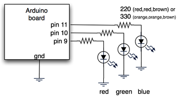
The hardware is just an Arduino board connected via USB to a laptop. The Arduino appears as a serial device to the computer. On the Arduino board, three LEDs (red,green,blue) are mounted directly to the Arduino board using a prototyping shield like this DIY one. The schematic is quite simple:
Arduino code
The code sketch running on the Arduino board is a slightly modified version of the one presented in the last Spooky Arduino class. Instead of parsing single color values over the serial port, it expects a full RGB color value in standard web format of “#RRGGBB” (white is “#ffffff”, blue is “#0000ff”, and so on). The sketch parses that seven character string into three bytes: one each for the brightness values of the red, green and blue LEDs.
Arduino code: serial_rgb_led_too.pde
Processing code
To bridge between the Arduino and the Net, a small Processing sketch was created that uses the standard Java HTTPURLConnection class to fetch a web page (really, a text file on a web server) containing a line with a color value in the format “#RRGGBB”. The sketch parses the color value, sends the value out to the Arduino orb using the Processing Serial library, and then sets its own background color to match. Because I’ve set the framerate of the sketch to 1 fps, it takes a second for the background to match the orb. I did this on purpose so I could get a sense of the color as the orb reproduces it before seeing it as it truly is. I was surprised how well the two tended to match!
Processing code: http_rgb_led.pde
Would it not be cooler to control thie colours via a POT? Pulsing the brightness woulld be cool too
Hi Tod,
great site. I have been trying arduino and processing using you bionic tutorials. Fantastic!!
I’m using arduino ide 1.0. When i load the potsend script I get an error
“BYTE word not supported use serial.write() instead.”
Do you have another version of potsend.?
I’m not a programmer so I cant get my head around the code
I suspect the error has to do with this part of the code:
port = new Serial(this, portstr, 9600);
Where portstr is defined as:
String portstr = “/dev/tty.usbserial-A3000Xv0”;
Can you help me to understand what “portstr” is for? I am using an Arduino UNO on COM3 port.
Hi,
I stumbled across your blog when Googling Ambient Orb. I am very interested in your work, and am trying to replicate what you did. I am completely new to all of this, but managed to get to the point where your Arduino code (serial_rgb_led_too.pde) now works for me really well!
I am stuck at the Processing code part. I downloaded the Processing IDE and your code (http_rgb_led.pde), but when I run your code I get the error below:
countdown to color: 3
countdown to color: 2
countdown to color: 1
countdown to color: 1
content: set the color
content: #9970ff
parsed color #9970ff
java.lang.NullPointerException
at processing.serial.Serial.write(Unknown Source)
at processing.serial.Serial.write(Unknown Source)
at http_rgb_led.getWebColor(http_rgb_led.java:82)
at http_rgb_led.draw(http_rgb_led.java:57)
at processing.core.PApplet.handleDraw(Unknown Source)
at processing.core.PApplet.run(Unknown Source)
at java.lang.Thread.run(Thread.java:662)
Can you help me by pointing out what I am doing wrong? I am completely stuck and any guidance would be greatly appreciated. Thank you!
I got it running, and it is super cool! I have a dedicated laptop so that it runs 24/7. Looking at the PHP, I see where the “pulse” idea is implemented, but I can’t follow it to the code running on the Arduino or in Processing. Am I crazy, or does it not exist? If I am sane, and it isn’t there, how would I go about implementing it?
Hi Daniel,
Can you please describe exactly what steps you are taking to produce that error? Also, what version of Arduino and what OS are you on?
10: error: #include expects “FILENAME” or <FILENAME
Does anyone know about this error code cant get past it need HELP?
Hi Tod!
Thx for this wounderful “project”! I am just wondering if I had missunderstand it a bit, or if it is just my computer that is a blit spoooooky!
For me, after a while the RGB LED starts to change color by it’s own. Is it ment to be like that?
If it is ment to be like that can you help me fix the code so it doesent make that? :)
// Nisse from Sweden :)
Hello everyone,
I was wondering if anyone has successfully implemented the ‘pulse’ idea. I have my arduino running my lamp and it looks beautiful; I would love it it it could “display” precipitation. Either pulse, or light up a separate LED or two.
Thanks!
Rick.
Hi Dave,
There are many examples of that on the Arduino forums and other places. The code is pretty short, basically just:
void loop() {
  int r = analogRead(redSlider) / 4;
  int g = analogRead(grnSlider) / 4;
  int b = analogRead(bluSlider) / 4;

  analogWrite( redPin, r );
  analogWrite( grnPin, g );
  analogWrite( bluPin, b );
}